Cisco : SPAN and Remote SPAN

As part of the CCNP Switch you get introduced to a topic called SPAN and Remote SPAN. This feature allows Network Engineers to capture packets flowing to and from a Interface or VLAN and mirror or forward those packets to a Packet Capture Analyzer software such as Wireshark.

Things to be aware of when setting SPAN and RSPAN up:

  • Make sure you destination port is of equivalent speed to the Source port otherwise you could drop packets.
  • A source port cannot be the same as a destination port
  • A destination port can only  be a part of one SPAN session
  • Source ports can be part of a EtherChannel but destinations ports cannot
  • Trunk ports can be setup as source and destination and the default behavior will monitor all active VLAN’s on that port
  • Destination Ports will not participate in STP, CDP, VTP, DTP or LACP
  • The number of SPAN sessions can vary on different switch models

The source can be set to entire VLAN’s (VSPAN) or individual ports. The Source is the port or VLAN you want to monitor.

Here is what the basic SPAN topology would look like:


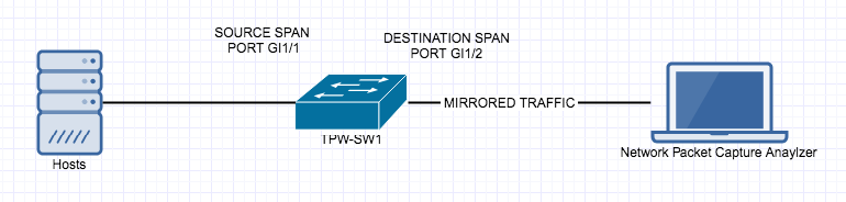
Here is how to setup the Source SPAN interface.


tpw-sw1(config)#monitor session 1 source interface GigabitEthernet 1/1

The Destination is the port you have the network analyzer connected to.

tpw-sw1(config)#monitor session 1 destination interface GigabitEthernet 1/2

Verify your SPAN port setup.

tpw-sw1#show monitor

Session 1

---------

Type                   : Local Session

Source Ports           :

    Both               : Gi1/1

Destination Ports      : Gi1/2


The behavior is expected on a SPAN port:

tpw-sw1#sh int Gi1/1
FastEthernet1/1 is down, line protocol is down (monitoring)


However SPAN isn’t always going to be local, so luckily for us there is Remote SPAN (RSPAN). This feature allows the mirrored packets to traverse the trunk port to another switch via a separate VLAN. The configuration is fairly straightforward however there are a couple of caveats:

  1. All switches have to be RSPAN capable.
  2. VTP does treat the RSPAN VLAN like a regular VLAN and will propagate that through the VTP domain, but if its not you will have to add them manually to each switch
  3. VTP will prune the VLANS like a regular VLAN
  4. MAC address learning is disabled on the RSPAN VLAN
  5. Source and Destinations will be slightly different on each switch so don’t just copy the commands on each switch.

The topology would look something like this:


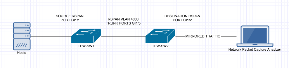
Here is the configuration for RSPAN tpw-sw1 – be  aware the destination RSPAN VLAN

tpw-sw1(config)#vlan 4000

tpw-sw1(config-vlan)#remote-span

tpw-sw1(config)#monitor session 1 source interface GigabitEthernet 1/1

tpw-sw1(config)#monitor session 1 destination remote vlan 4000

Verify your work.

tpw-sw1#show monitor

Session 1

---------

Type                   : Local Session

Source Ports           :

    Both               : Gi1/1

Dest RSPAN VLAN     : 4000

Here is the configuration for RSPAN tpw-sw2 – be aware the source is the RSPAN VLAN

tpw-sw2(config)#vlan 4000

tpw-sw2(config-vlan)#remote-span

tpw-sw2(config)#monitor session 1 source remote vlan 4000

tpw-sw2(config)#monitor session 1 destination interface GigabitEthernet 1/2

Verify your work.

tpw-sw2#show monitor

Session 1

---------

Type                   : Local Session

Source RSPAN VLAN        : 4000

Destination Ports     : Gi1/2


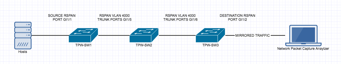
If you have a setup similar to below you have to name Remote SPAN VLAN 4000 on all intermediate switches.

Happy SPANNING 🙂


Linux/Mac Networking Commands

I have been gathering a bunch of Linux/Mac Commands that I have found useful, hopefully someone else will find this list useful.

Run a speed test from CLI:

curl -s https://raw.githubusercontent.com/sivel/speedtestcli/master/speedtest.py | python -

Get an ip address for en0:

ipconfig getifaddr en0

Same thing, but setting and echoing a variable:

ip=`ipconfig getifaddr en0` ; echo $ip

View the subnet mask of en0:

ipconfig getoption en0 subnet_mask

View the dns server for en0:

ipconfig getoption en0 domain_name_server

Get information about how en0 got its dhcp on:

ipconfig getpacket en1

View some network info:

ifconfig en0

Set en0 to have an ip address of 10.10.10.10 and a subnet mask of 255.255.255.0:

ifconfig en0 inet 10.10.10.10 netmask 255.255.255.0

Show a list of locations on the computer:

networksetup -listlocations

Obtain the active location the system is using:

networksetup -getcurrentlocation

Create a network location called Work and populate it with information from the active network connection:

networksetup -createlocation Work populate

Delete a network location called Work:

networksetup -deletelocation Work

Switch the active location to a location called Work:

networksetup -switchlocation Work

Switch the active location to a location called Work, but also show the GUID of that location so we can make scripties with it laters:

scselect Work

List all of the network interfaces on the system:

networksetup -listallnetworkservices

Rename the network service called Ethernet to the word Wired:

networksetup -renamenetworkservice Ethernet Wired

Disable a network interface:

networksetup -setnetworkserviceenabled off

Change the order of your network services:

networksetup -ordernetworkservices “Wi-Fi” “USB Ethernet”

Set the interface called Wi-Fi to obtain it if it isn’t already

networksetup -setdhcp Wi-Fi

Renew dhcp leases:

ipconfig set en1 BOOTP && ipconfig set en1 DHCP

ifconfig en1 down && ifconfig en1 up

Renew a dhcp lease in a script:

echo "add State:/Network/Interface/en0/RefreshConfiguration temporary" | sudo scutil

Configure a manual static ip address:

networksetup -setmanual Wi-Fi 10.0.0.2 255.255.255.0 10.0.0.1

Configure the dns servers for a given network interface:

networksetup -setdnsservers Wi-Fi 10.0.0.2 10.0.0.3

Obtain the dns servers used on the Wi-Fi interface:

networksetup -getdnsservers Wi-Fi

Stop the application layer firewall:

launchctl unload /System/Library/LaunchAgents/com.apple.alf.useragent.plist
launchctl unload /System/Library/LaunchDaemons/com.apple.alf.agent.plist

Start the application layer firewall:

launchctl load /System/Library/LaunchDaemons/com.apple.alf.agent.plist
launchctl load /System/Library/LaunchAgents/com.apple.alf.useragent.plist

Allow an app to communicate outside the system through the application layer firewall:

socketfilterfw -t
“/Applications/FileMaker Pro/FileMaker Pro.app/Contents/MacOS/FileMaker Pro”

See the routing table of a Mac:

netstat -nr

Add a route so that traffic for 10.0.0.0/32 communicates over the 10.0.9.2 network interface:

route -n add 10.0.0.0/32 10.0.9.2

Log bonjour traffic at the packet level:

sudo killall -USR2 mDNSResponder

Stop Bonjour:

launchctl unload -w /System/Library/LaunchDaemons/com.apple.mDNSResponder.plist

Start Bojour:

launchctl load -w /System/Library/LaunchDaemons/com.apple.mDNSResponder.plist

Put a delay in your pings:

ping -i 5 192.168.210.1

Ping the hostname 5 times and then stop the ping:

ping -c 5 google.com

Flood ping the host:

ping -f localhost

Set the packet size during your ping:

ping -s 100 google.com

Customize the source IP during your ping:

ping -S 10.10.10.11 google.com

View disk performance:

iostat -d disk0

Get information about the airport connection on your system:

/System/Library/PrivateFrameworks/Apple80211.framework/Versions/A/Resources/airport -I

Scan the available Wireless networks:

/System/Library/PrivateFrameworks/Apple80211.framework/Versions/A/Resources/airport -s

Trace the path packets go through:

traceroute google.com

Trace the routes without looking up names:

traceroute -n google.com

Trace a route in debug mode:

traceroute -d google.com

View information on all sockets:

netstat -at

View network information for ipv6:

netstat -lt

View per protocol network statistics:

netstat -s

View the statistics for a specific network protocol:

netstat -p igmp

Show statistics for network interfaces:

netstat -i

View network information as it happens (requires ntop to be installed):

ntop

Scan port 80 of www.google.com

/System/Library/CoreServices/Applications/Network\ Utility.app/Contents/Resources/stroke www.google.com 80 80

Port scan krypted.com stealthily:

nmap -sS -O krypted.com/24

Establish a network connection with www.apple.com:

nc -v www.apple.com 80

Establish a network connection with gateway.push.apple.com over port 2195

/usr/bin/nc -v -w 15 gateway.push.apple.com 2195

Establish a network connection with feedback.push.apple.com only allowing ipv4

/usr/bin/nc -v -4 feedback.push.apple.com 2196

Setup a network listener on port 2196 for testing:

/usr/bin/nc -l 2196

Capture some packets:

tcpdump -nS

Capture all the packets:

tcpdump -nnvvXS

Capture the packets for a given port:

tcpdump -nnvvXs 548

Capture all the packets for a given port going to a given destination of 10.0.0.48:

tcpdump -nnvvXs 548 dst 10.0.0.48

Capture the packets as above but dump to a pcap file:

tcpdump -nnvvXs 548 dst 10.0.0.48 -w /tmp/myfile.pcap

Read tcpdump (cap) files and try to make them human readable:

tcpdump -qns 0 -A -r /var/tmp/capture.pcap

What binaries have what ports and in what states are those ports:

lsof -n -i4TCP

Make an alias for looking at what has a listener open, called ports:

alias ports='lsof -n -i4TCP | grep LISTEN'

Report back the name of the system:

hostname

Flush the dns cache:

dscacheutil -flushcache

Clear your arp cache:

arp -ad

View how the Server app interprets your network settings:

serveradmin settings network

Whitelist the ip address 10.10.10.2:

/Applications/Server.app/Contents/ServerRoot/usr/libexec/afctl -w 10.10.10.2


Test Connectivity with Telnet

Telnet is a Network protocol that allows users to connect to and administer a devices Command Line Interface (CLI). However all of the information exchanged on a Telnet session is unencrypted, this means is someone is sniffing the traffic from your host to the device it can be read clearly. So now all know telnet is a super un-secure way to access the CLI of a device, and you should always use SSH where you can, but Telnet can be used in another way. Telnet can only be used to verify network connectivity to remote devices that are TCP based, because TCP is a connection-oriented protocol.

I get requests all the time to open up specific ports on the firewall. You can find a list of the well know port numbers here.

Before I start poking holes in the firewall or other device I check to see if it is already open.

Telnet will by default only check and listen on TCP port 23

If a user asks me is https (port 443) is open to and on a specific server you can easily test with Telnet.

You simply add the port number at the end of the telnet command:

 telnet[host/address[port]]


As you can see 443 is open. To exit from the Telnet session: 

SHIFT ]


This telnet test to port 23 is not open as it does not say Connected to…


If a remote host does not respond to telnet it can mean a number of things.

  1. The Firewall or Firewalls or other networking devices on the path to the remote host is Denying or Dropping the packets. You will be able to confirm that in the logs on the firewall.
  2. The server or remote host on the other side is not up and active
  3. There is no connectivity to the remote host for some other reason

Further troubleshooting is required if you encounter issues.

Common Port Numbers

Common TCP/IP Protocols and Ports

Protocol TCP/UDP Port Number
File Transfer Protocol (FTP)

(RFC 959)

TCP 20/21
Secure Shell (SSH)

(RFC 4250-4256)

TCP 22
Telnet

(RFC 854)

TCP 23
Simple Mail Transfer Protocol (SMTP)

(RFC 5321)

TCP 25
Domain Name System (DNS)

(RFC 1034-1035)

TCP/UDP 53
Dynamic Host Configuration Protocol (DHCP)

(RFC 2131)

UDP 67/68
Trivial File Transfer Protocol (TFTP)

(RFC 1350)

UDP 69
Hypertext Transfer Protocol (HTTP)

(RFC 2616)

TCP 80
Post Office Protocol (POP) version 3

(RFC 1939)

TCP 110
Network Time Protocol (NTP)

(RFC 5905)

UDP 123
NetBIOS

(RFC 1001-1002)

TCP/UDP 137/138/139
Internet Message Access Protocol (IMAP)

(RFC 3501)

TCP 143
Simple Network Management Protocol (SNMP)

(RFC 1901-1908, 3411-3418)

TCP/UDP 161/162
Border Gateway Protocol (BGP)

(RFC 4271)

TCP 179
Lightweight Directory Access Protocol (LDAP)

(RFC 4510)

TCP/UDP 389
Hypertext Transfer Protocol over SSL/TLS (HTTPS)

(RFC 2818)

TCP 443
Lightweight Directory Access Protocol over TLS/SSL (LDAPS)

(RFC 4513)

TCP/UDP 636
FTP over TLS/SSL

(RFC 4217)

TCP 989/990
The complete list of assigned ports and their assigned services can be seen at http://www.iana.org/assignments/service-names-port-numbers/service-names-port-numbers.xml.

The Packet Wizard : DHCP Troubleshooting

In todays scenario, I am going to walk through some changes I made and troubleshooting steps for when I recently added a moved a old SSID/Subnet off an old legacy wireless network onto a new network same IP space and SSID that requires RADIUS authentication.

These steps can be applied to many different scenarios for troubleshooting DHCP, I just made these ones specific since it was something I recently had to troubleshoot.

Here is a basic diagram of the setup, showing all the moving parts would be overkill for the diagram. The steps on what to do and troubleshooting are below the diagram.

What you will need:

Authentication Server IP

Authentication Secret Key

DHCP Server IP

Subnet and Mask that is being moved

SSID/Subnet being moved

Work and or Troubleshooting that needs to be done:

  1. Add the VLAN to the switches required
  2. Add the virtual interface on the firewall (gateway)
  3. Trunk the new vlan to the switch and configure the ports
  4. Setup DHCP helper to point to the DHCP server
  5. Allow DHCP traffic from the new subnet to the DHCP server
  6. Configure Radius on new Network
  7. Configure new SSID and network settings on Wireless LAN Controller

Cisco : Enable SSH on Cisco Switch, Router and ASA

When you configure a Cisco device, you need to use a console cable and connect directly to the system to access it. Follow the SSH setup below, will enable SSH access to your Cisco devices, since SSH is not enabled by default. Once you enable SSH, you can then access it remotely using SecureCRT or any other SSH client.

Set hostname and domain-name

The hostname has to have a hostname and domain-name.

switch# config t
switch(config)# hostname tpw-switch
tpw-switch(config)# ip domain-name thepacketwizard.com

Setup Management IP

In the following example, the management ip address will be set to 10.100.101.2 in the 101 VLAN. The default gateway points to the firewall, which is 10.100.101.1

tpw-switch# ip default-gateway 10.100.101.1
tpw-switch# interface vlan 101
tpw-switch(config-if)# ip address 10.100.101.2 255.255.255.0

Generate the RSA Keys

The switch or router should have RSA keys that it will use during the SSH process. So, generate these using crypto command as shown below.

tpw-switch(config)# crypto key generate rsa
  The name for the keys will be: tpw-switch.thepacketwizard.com
  Choose the size of the key modulus in the range of 360 to 2048 for your
    General Purpose Keys. Choosing a key modulus greater than 512 may take
    a few minutes.

How many bits in the modulus [512]: 1024
  % Generating 1024 bit RSA keys, keys will be non-exportable...[OK]

Setup the Line VTY configurations

Setup the following line vty configuration, where input transport is set to SSH only. Set the login to local, and password to 7, and make sure Telnet is not enabled:

tpw-switch# line vty 0 4
 tpw-switch(config-line)# transport input ssh
 tpw-switch(config-line)# login local
 tpw-switch(config-line)# password 7
 tpw-switch(config-line)# exit

If you have not set the console line yet, use the following:

tpw-switch# line console 0
tpw-switch(config-line)# logging synchronous
tpw-switch(config-line)# login local

Create the username password

If you don’t have an username created already, here is how:

tpw-switch# config t
Enter configuration commands, one per line.  End with CNTL/Z.
tpw-switch(config)# username thepacketwizard password tpwpassword123
tpw-switch# enable secret tpwenablepassword

Make sure the password-encryption service is turned-on, which will encrypt the password, and when you do “show run”, you’ll see only the encrypted password and not clear-text password.

tpw-switch# service password-encryption

Verify SSH access

From the switch, if you do ‘show ip ssh’, it will confirm that the SSH is enabled on this Cisco device.

tpw-switch# show ip ssh
 SSH Enabled - version 1.99
 Authentication timeout: 120 secs; Authentication retries: 3

After the above configurations, login from a remote machine to verify that you can ssh to this cisco switch.

In the example, 10.100.101.2 is the management ip-address of the switch.

TPW-Remote-Computer# ssh 10.100.101.2
 login as: thepacketwizard
 Using keyboard-interactive authentication.
 Password:

tpw-switch>en
 Password:
 tpw-switch#

You are now setup and logged in on SSH!

To read more on SSH visit: https://en.wikipedia.org/wiki/Secure_Shell

Palo Alto : Upgrade High Availability (HA) Pair

Over the last 3 weeks since the Christmas and New Year Holidays,  I have been upgrading all of our firewalls globally, many of them are an High Availability Pair. This means they are redundant and being redundant allows me to upgrade them individually while the site stays full up and functional.

The  instructions for upgrading an HA pair are recommended because:

      • It verifies HA functionality before starting the upgrade.
      • It ensures the upgrade is successfully applied to the first device before starting the upgrade on the second.
      • At any point in the procedure, if any issue arises, the upgrade can be seamlessly reverted without any expected downtime (unless you are having any dynamic routing protocols line OSPF/BGP).
      • When finished, the final active/passive device state will be the same as it was before the upgrade with the fewest number of fail overs possible (2).

Before you Begin :

Take backup of the configuration as well as Tech Support from both HA Peers. Give proper names to each file, here is how:

Device > Setup > Operations > Save Named Configuration Snapshot

Device > Setup > Operations > Export Named configuration Snapshot

Device > Setup > Operations > Export Device State (If device managed from panorama

Device > Support > Generate Tech Support File, and then download it. (Might be required if any issues)

(Optional but recommended) Disable preemption on High Availability settings to avoid the possibility of unwanted failovers. Disabling preempt configuration change must be committed on both peers. Likewise, once completed, re-enabling must be committed on both peers.

To disable preempt, go to

Device > High Availability > Election Settings and uncheck Preemptive.
Then, perform a commit.


If upgrade is between major versions (4.1 -> 5.0 OR 5.0-> 6.0), it is advisable to disable TCP-Reject-Non-SYN, so that sessions can failover even when they are not in sync. : Do this on both Firewalls from the CLI:

 # set deviceconfig setting session tcp-reject-non-syn no
 # commit


(Optional but recommended) Arrange for Out-of-Band access (Console access) to the firewall if possible. This is again to help recover from any unexpected situation where we are unable to login to the firewall. If you have a Terminal Server awesome, if not a simple Cell Phone tethered to a Laptop with RDP is also fine.


The Upgrade Process

Suspend Backup Device 

From the CLI

 > request high-availability state suspend

From the GUI

Go to Device > High Availability > Operational Commands  > Suspend local device

Install the new PAN-OS on the suspended device

Device > Software > Install

Reboot the device to complete the install.

When the upgraded device is rebooted, check the dashboard to check the version, wait for all the interfaces to come backup green.

If the device is still in suspended state make it functional again

From the CLI

> request high-availability state functional

From the GUI

Go to Device > High Availability > Operational Commands  > Make Local Device Functional


Repeat steps on other firewall.


Suspend Primary Device

From CLI

> request high-availability state suspend

From the GUI

Go to Device > High Availability > Operational Commands  > Suspend local device.


*The Backup Firewall will become Active – it does take 30-45 seconds so don’t panic


Install the new PAN-OS on the suspended device:

Device > Software > Install

Reboot the device to complete the install.

When the upgraded device is rebooted, check the dashboard to check the version, wait for all the interfaces to come backup green.

If the device is still in suspended state make it functional again

From the CLI

> request high-availability state functional

From the GUI

Go to Device > High Availability > Operational Commands  > Make Local Device Functional

To Get Primary Back to Primary by suspending the backup (current active) firewall (The Original Backup Firewall)

From the GUI,

Go to Device > High Availability > Operational Commands  > Suspend local device.

Once the Primary became active again, enable the suspended backup firewall

Enable TCP-Reject-Non-SYN, so that sessions can failover even when they are not in sync. : (Do this on both Firewalls)

# set deviceconfig setting session tcp-reject-non-syn yes
# commit


Re-Enable preempt configuration change must be committed on both peers. To re-enable preempt, go to Device > High Availability > Election Settings and uncheck Preemptive.  Then, perform a commit.


How to Downgrade

If an issue occurs on the new version and a downgrade is necessary:

To revert to the previous PAN-OS screen, run the following CLI command:

# debug swm revert

This causes the firewall to boot from the partition in use prior to the upgrade. Nothing will be uninstalled and no configuration change will be made.


However please be aware while running this command –

After rebooting from a SWM revert, the configuration active at the time before upgrade will be loaded with the activation of the previous partion. Any configuration changes made after upgrade will not be accounted for and will need to be manually recovered by loading the latest configuration version and committing the changes.

General Troubleshooting : How to determine the proper MTU size with ICMP pings

How to determine the proper MTU size with ICMP pings

To find the proper MTU size, you have to run a special ping to the destination address. This is usually the gateway, local server or an IP address domain name internet (e.g. thepacketwizard.com). You probably want to start around 1800 and move down 10 each time until you get to a ping reply. Once you have a ping reply start moving backup by 2-5 bits to get to the fragmented packet size. Take that value and add 28 to the value to account for the various TCP/IP headers. E.g. let’s say that 1452 was the proper packet size (where you first got an ICMP reply to your ping). The actual MTU size would be 1480, which is the optimum for the network we’re working with. Header size varies depending what the packet is traversing.


1500 Standard MTU

– 20 IP Header

– 24 GRE Encaps.

– 52 IPSec Encap.

– 8 PPPoE

– 20 TCP Header


Windows

ping  (host) (-f) (-l (packet size))

An example would be:

ping  thepacketwizard.com -f -l 1800

(result = "Packet needs to be fragmented but DF set.")

ping thepacketwizard.com -f -l 1472 

(result = reply)


The options used are:

      • -f: set “Don’t Fragment” flag in packet
      • -l size: send buffer size


Linux

ping (-M do) (-s (packet size)) (host)

An example would be:

ping thepacketwizard.com -M do -s 1800

(result = "Frag needed and DF set" or "message too long")

ping thepacketwizard.com -M do -s 1472

(result = reply)


The options used are:

      • -M <hint>: Select Path MTU Discovery strategy. <hint> may be either “do” (prohibit fragmentation, even local one), “want” (do PMTU discovery, fragment locally when packet size is large), or “dont” (do not set DF flag).
      • -s packetsize: Specifies the number of data bytes to be sent. The default is 56, which translates into 64 ICMP data bytes when combined with the 8 bytes of ICMP header data.


Mac

ping (-D) (-s (packet size)) (host)

An example would be:

ping thepacketwizard.com -D -s 1800

(result = "sendto: Message too long")

ping thepacketwizard.com -D -s 1462

(result = reply)


The options used are:

      • -D: set the “Don’t Fragment” bit
      • -s packetsize: Specify the number of data bytes to be sent. The default is 56, which translates into 64 ICMP data bytes when combined with the 8 bytes of ICMP header data.

There is a lot to know about MTU check it out on Wikipedia : Wikipedia – MTU

Palo Alto : Enable IPv6 and Create Default Route

To Enable IPv6 on the Firewall

Web GUI

IPv6 firewalling is enabled under Device > Setup > Session:

*** You may have to restart your Firewall for IPv6 to be enabled.

On the CLI

> configure

# set deviceconfig setting session ipv6-firewalling [yes|no]

# commit

Here is the interface configuration I used:

Don’t forget to add a rule in your security policy that allows Your new IPv6 interface to talk to your Gateway.

Add Default Route

You will also have to add a default route under Network > Virtual Routers > Default > Static Routes > IPv6

The default route for IPv6 is ::/0 the next hop is the default gateway address

Cisco : Serial Numbers

Today I have spent some time trying to find serial numbers on multiple Cisco devices, some Routers, Switches, Firewalls and Wireless LAN Controllers. Here is 7 ways I have found:

  1. Locate the serial number tag on the device chassis.
  2. The serial number is displayed in the banner during boot.
  3. “show version” command. (Look for Processor board ID or S/N)
  4. “show inventory” command. (Look for Hw Serial# or SN:)(Also works on WLC’s)
  5. “show diag” command. (Look for Chassis Serial Number)
  6. “show hardware” command. (Look for Processor board ID or S/N)
  7. “show tech-support” command.