Ruckus : Using Multiple RADIUS Servers

I have recently been configuring Network Access Control with 802.1x, and I had been having issues with using multiple RADIUS servers on Ruckus ICX Switches. The main issue being:

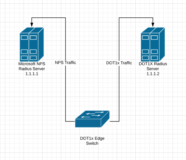
RADIUS Authenticate over SSH to switch using Microsoft NPS RADIUS Server
RADIUS Authenticate using 802.1x or MAC-Auth using DOT1x RADIUS Server

In Ruckus ICX switches there isn’t any concept of AAA groups like in Cisco, where you can designate specific RADIUS traffic to go to various different RADIUS Servers.

I have found 2 work arounds, I did however also call support and spend 1 hour troubleshooting with them and they didn’t have an answer for me.

Some Basic Setup Information

Microsoft NPS RADIUS Server : 1.1.1.1
DOT1x RADIUS Server : 1.1.1.2

Here are my AAA Authentication Commands:

SSH@tpw-sw1# sh run | inc authentication
aaa authentication web-server default radius local
aaa authentication enable default radius local
aaa authentication dot1x default radius
aaa authentication login default radius local

Here are my 2 work arounds:

WORKAROUND 1

SSH@tpw-sw1(config)# radius-server host 1.1.1.1 auth-port 1812 acct-port 1813 default key RADIUS1SECRET
SSH@tpw-sw1(config)# radius-server host 1.1.1.2 auth-port 1812 acct-port 1813 default key RADIUS2SECRET dot1x mac-auth

If you use the 1.1.1.2 RADIUS server first in the list you cannot authenticate to the switch at all, even over super-user-password. So the only way I have it working is to have the DOT1x Radius Server listed 2nd but calling out DOT1x and MAC-AUTH.

WORKAROUND 2

The other method I found is to apply a command at the interface level:

SSH@tpw-sw1# conf t
SSH@tpw-sw1(config)# int ethernet 1/1/1
SSH@tandy-lab-sw1(config-if-e1000-1/1/1)#use-radius-server 1.1.1.2

I hope that this helps, I spent a day trying to figure it out 🙂


The Packet Wizard : Multicast

This week I have been troubleshooting a Multicast problem, before Tuesday I knew the basics of it but I did not realize how deep that rabbit hole went, I can only imagine how deep it goes in CCIE level since it has not really crossed my path in any of my studies thus far. I thought I should write this blog post to share what I have learned this week about Multicast. I will also write another post on how to configure and troubleshoot it.

What is Multicast?

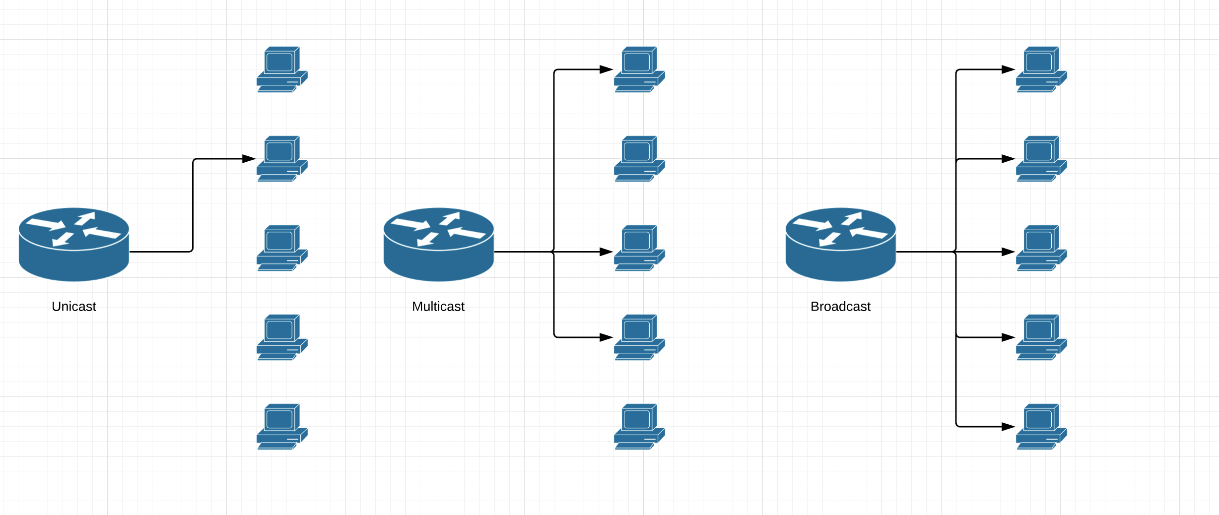
Multicast is a group communication where data packets are sent to a group of receiver/destination computers at the same time. Multicast is one to many or many to many real time communication protocol, where Unicast is one to one and Broadcast is one to all. Multicast is mainly used in IPTV (Netflix, Hulu, Prime Video).

Multicast Address Ranges


They use Class D Range – 224.0.0.0 – 239.255.255.255

224.0.0.0 224.0.0.255 – Reserved for Local Addresses

224.0.1.0 – 238.255.255.255 – Globally Scoped Addresses

232.0.0.0 – 232.255.255.255 – Source Specific Multicast Addresses

233.0.0.0 – 233.255.255.255 – GLOP Addresses

239.0.0.0 – 239.255.255.255 – Limited Scope Address (Similar to Private IP addresses but for Multicast)


How does Multicast Work?

The Receiver sends a packet to the Router asking to Join the Multicast Group. Only the clients that want to receive Multicast join what is called a Multicast Group. If the router doesn’t know about it it will send requests out its next hop interface.

Protocol Independent Multicast (PIM) Think of this like a multicast routing protocol sits on top of the Internet Group Management Protocol (IGMP) and builds a pipe back to the source from the destination. There are 3 versions of IGMP:

IGMPv1 – has a 60 second timer and continually asks.
IGMPv2 – can send an I want to leave the multicast group message to the router.
IGMPv3 – can include a source in the join packets.

If the multicast sender has multiple paths to the receiver it will send the multicast multi ways meaning the receiver will receive duplicate messages. The receiver then has to send the reply but it uses the unicast routing table to return the traffic and uses that interface.


Reverse Path Forwarding (RPF) is a check that the receiving device does before the sender sends anything so it knows how to get back to get back to the sender without receiving multiple multicast messages.


Multicast Types

I am sure there are more than two types of multicast but all I have covered are Sparse and Dense mode.

Sparse Mode is like a Join Protocol, where traffic is not forwarded on a segment unless it is explicitly requested. Sparse mode is typically deployed where the receivers are sparsely populated over the network, so that most of the network bandwidth is conserved.

Dense Mode is like a flood and prune system, where everyone receives the traffic until they inform (through the prune system) that they do not want that particular multicast messages. Dense Mode is typically deployed in topologies where listeners are densely populated, but it can be a very chatty protocol.

You can setup sparse mode or dense mode on a per interface basis. Once they are setup and enabled interfaces can run sparse mode while others run dense mode.

A Networking genius (Denise Fishburne – https://www.networkingwithfish.com/ ) said on a training video I watched yesterday “Friends don’t let friends do dense mode”. Denise also recently started following my blog, which is a huge honor. I hope this post is doing some basic justice to Multicast. I am trying to share information I have gathered in the last couple of days. If anyone has any comments or further insight let me know.


The Packet Wizard : Migrating from Cisco 6500 to Ruckus ICX

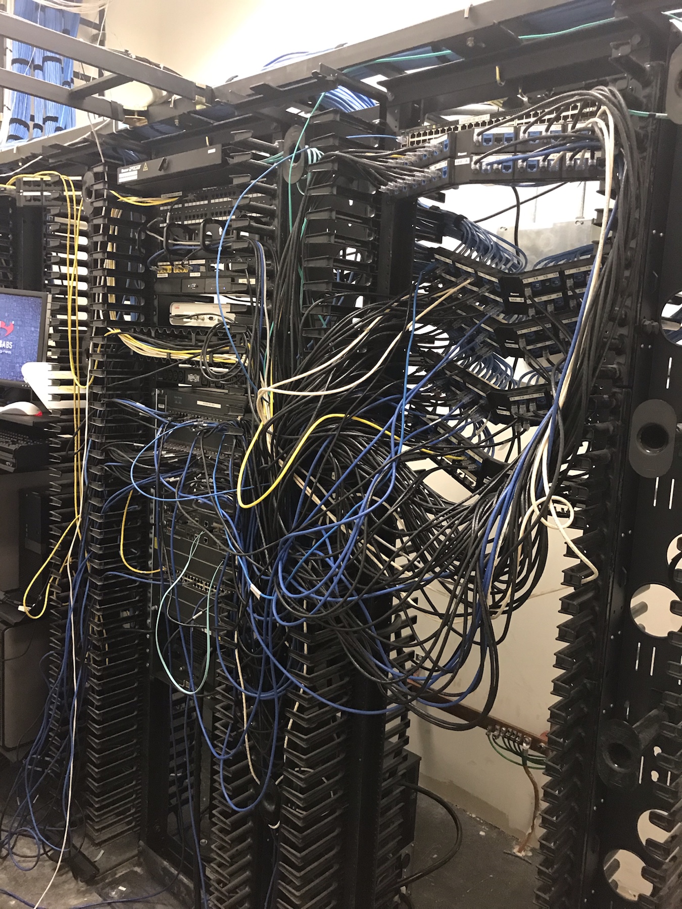
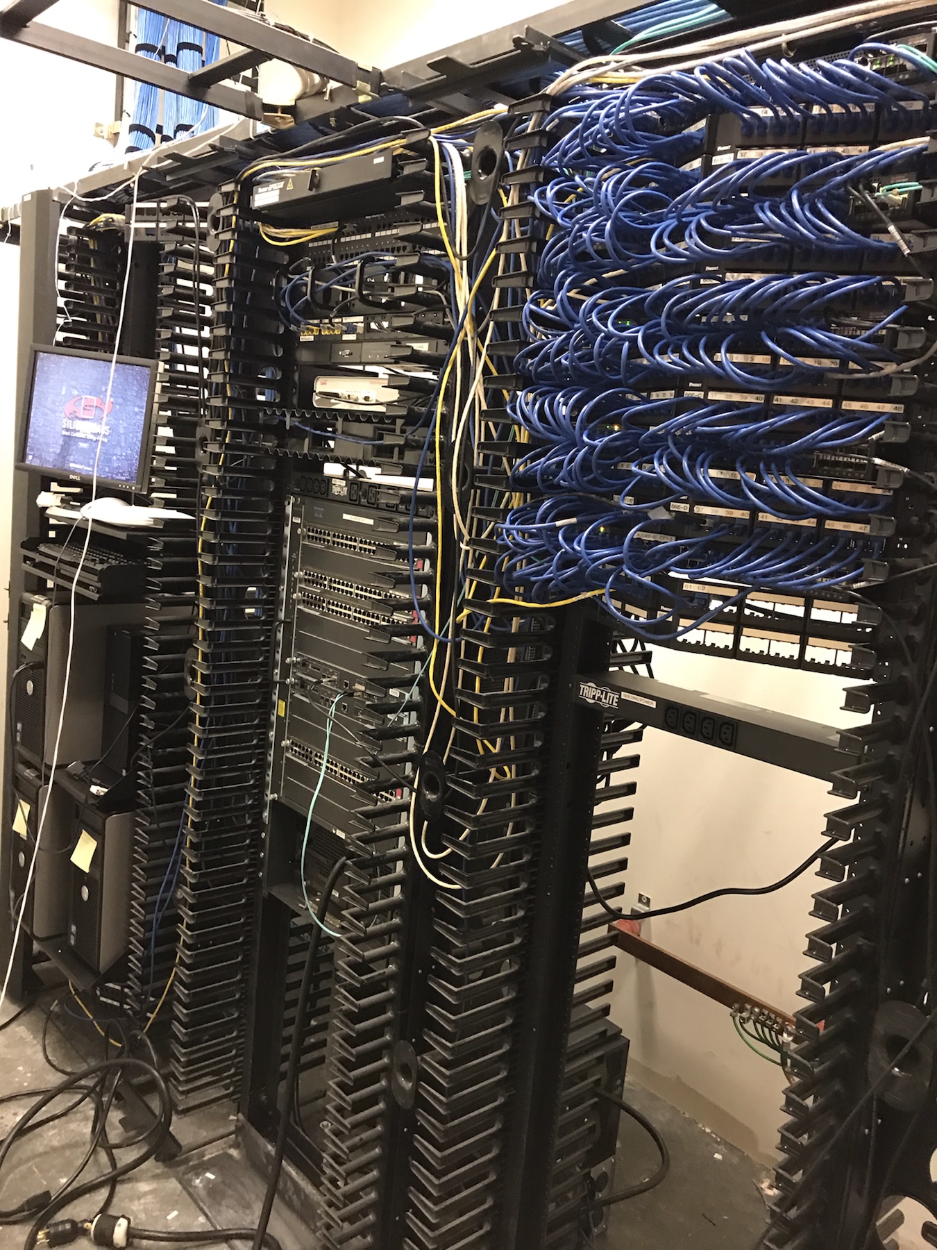
Just a quick post this week, I have been busy migrating from Cisco 6500 to Ruckus ICX. Here are some before and after photos and a video of the all important turn off. The main thing I learned in this migration is to chose your ports that are different, do Trunk Ports, Wireless, Printers, anything that is unique or requires a slightly different configuration do them first, then the regular desktop/user ports are just easy swaps.

The before picture we had already started to move the patch panels.

Listen to that power noise drop when it turns off. Turning off Cisco 6500 after Migration

Cisco Switch : Private VLAN’s

Private VLAN’s are a very interesting and mostly used for Network segmentation and fun concept but it can take a little to get your head around, so here goes.

Private VLAN’s split a VLAN into Sub-VLANs, called Primary and Secondary.  Secondary VLAN’s have 2 different types :  Isolated and Community.

In this example the Primary VLAN is 100 and the Secondary VLAN’s are Isolated VLAN 200, Community VLAN 300 and Community VLAN 400.
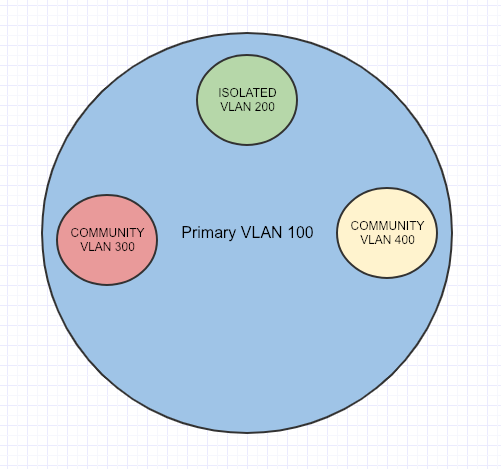
An important port to know about before beginning is called the Promiscuous Port. It acts like a Gateway that routes Primary and Secondary-VLAN traffic, and all Secondary-VLAN traffic must pass through the Promiscuous Port.

Isolated ports can only talk to the Primary VLAN through a Promiscuous Port (Uplink/Gateway Port)

Community ports can talk to each other, if they are in the same Community Secondary-VLAN.

VTP must be set to transparent mode for Private VLAN’s to work.
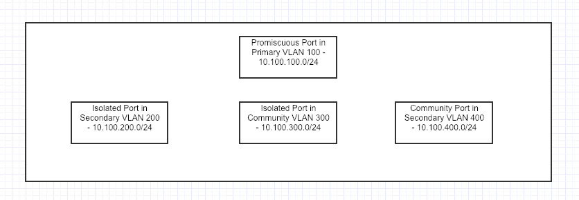
Here is how to configure Private VLAN’s

First we need to configure the Primary VLAN

TPW-SW1(config)#vlan 100
TPW-SW1(config-vlan)#private-vlan primary 
TPW-SW1(config-vlan)#exit

Configure the Isolated VLAN

TPW-SW1(config)#vlan 200
TPW-SW1(config-vlan)#private-vlan isolated 
TPW-SW1(config-vlan)#exit

Configure the Community VLAN’s

TPW-SW1(config)#vlan 300
TPW-SW1(config-vlan)#private-vlan community 
TPW-SW1(config-vlan)#exit

TPW-SW1(config)#vlan 400
TPW-SW1(config-vlan)#private-vlan community 
TPW-SW1(config-vlan)#exit

Now we have to associate the Primary VLAN to the Isolated and Community VLAN’s

TPW-SW1(config)#vlan 100 
TPW-SW1(config-vlan)#private-vlan association 200 
TPW-SW1(config-vlan)#private-vlan association 300
TPW-SW1(config-vlan)#private-vlan association 400

This is where we configure for fa0/1 as the Promiscuous Port

TPW-SW1(config-if)# int fa0/1 
TPW-SW1(config-if)#switchport mode private-vlan promiscuous

We have to tell the Promiscuous Port that it is associated with the  (Isolated and Community VLAN’s) that it can also see and talk to them appropriately.

TPW-SW1(config-if)#switchport private-vlan host-association 100 200,300,400
TPW-SW1(config-if)#exit

Configure fa0/2 and fa0/7 as the Isolated port, but also about its Primary VLAN 100

TPW-SW1(config-if)# int fa0/2 
TPW-SW1(config-if)#switchport mode private-vlan host
TPW-SW1(config-if)#switchport private-vlan host-association 100 200
TPW-SW1(config-if)#exit

TPW-SW1(config-if)# int fa0/7 
TPW-SW1(config-if)#switchport mode private-vlan host 
TPW-SW1(config-if)#switchport private-vlan host-association 100 200 
TPW-SW1(config-if)#exit

Configure fa0/3 and 4 as community ports, but also about its Primary VLAN 100

TPW-SW1(config)#int range fa0/3 - 4 
TPW-SW1(config-if-range)# 
TPW-SW1(config-if-range)# switchport mode private-vlan host
TPW-SW1(config-if-range)# switchport private-vlan host-association 100 300
TPW-SW1(config-if-range)# exit

Configure fa0/5 and 6 as community ports, but also about its Primary VLAN 100

TPW-SW1(config)#int range fa0/5 - 6 
TPW-SW1(config-if-range)# 
TPW-SW1(config-if-range)# switchport mode private-vlan host
TPW-SW1(config-if-range)# switchport private-vlan host-association 100 400
TPW-SW1(config-if-range)# exit

You can confirm the Private VLAN’s are setup correctly with the following show command

TPW-SW1#show vlan private-vlan

Primary      Secondary    Type                Ports
-------      ---------    -----------------   ----------------------------------
100          200          isolated            fa0/2, fa0/7
100          300          community           fa0/3, fa0/4
100          400          community           fa0/5, fa0/6

Here is the topology of what was just built.
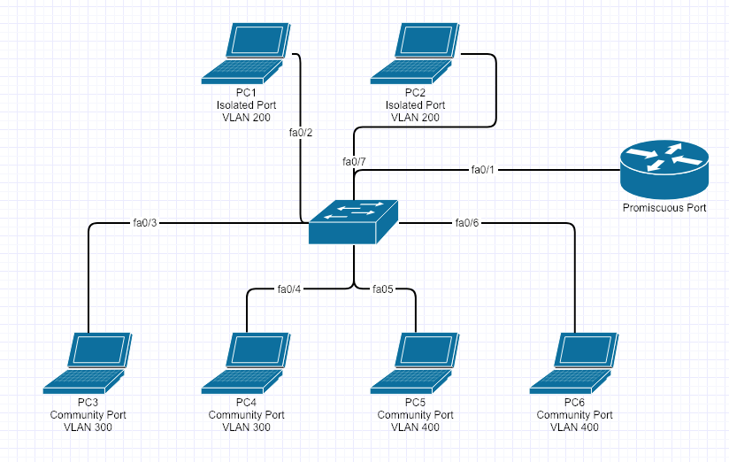
Here is a table of what can talk to each other

PC

Computer PC1 – Isolated – VLAN 200 PC2 – Isolated – VLAN 200 PC3 – Community VLAN 300 PC4 – Community VLAN 300 PC5 – Community VLAN 400 PC6 – Community VLAN 400
PC1 – Isolated – VLAN 200 YES NO NO NO NO NO
PC2 – Isolated – VLAN 200 NO YES NO NO NO NO
PC3 – Community VLAN 300 NO NO YES YES NO NO
PC4 – Community VLAN 300 NO NO YES YES NO NO
PC5 – Community VLAN 400 NO NO NO NO YES YES
PC6 – Community VLAN 300 NO NO NO NO YES YES


Cisco Switch : Dynamic ARP Inspection

Dynamic ARP inspection, starts with a man in the middle attack, with the rogue user and PC sending a gratuitous ARP to say the MAC address for your default gateway is this, then the user accessing anything using the default gateway is sending all its traffic to the rogue users pc, which is then copying all the packets before sending it on to its destination.


DHCP snooping must be enabled, for DAI to be enabled.


Here is how to configure DAI:

tpw-sw1(conf)# ip arp inspection vlan 10
tpw-sw1(conf)# int gi0/1
tpw-sw1(config-int)#ip arp inspection trust


How to Check and Verify DAI:

tpw-sw1# show ip arp inspection

Cisco Switch : Storm Control

Storm Control can shut down an interface that is causing a Unicast, Multicast or Broadcast Storm. It works with Rising and Falling Thresholds. If a specific type of traffic hits the rising Threshold it will block that type of traffic until the number of packets it see’s is below the set falling threshold. This can be in Percentage, Bits Per Second or Packets Per Second

Here is how to enable its various options:

tpw-sw1(conf)# int gi0/1
tpw-sw1(config-int)# storm-control broadcast level 10 5 - this command means if I see more than 10% broadcast traffic I will block until I see it fall under 5%
tpw-sw1(conf)# int gi0/1
tpw-sw1(config-int)# storm-control multicast level bps 20m 10m - this command means if I see more than 20Mbps multicast traffic I will block until I see it fall under 10Mbps
tpw-sw1(conf)# int gi0/1
tpw-sw1(config-int)# storm-control unicast level pps 50k  - this command means if I see more than 50,000 unicast packets per second, I will drop traffic until I see it fall below 50,000 packers per second, that is what happens if you do not put a falling threshold. Both rising and falling threshold is 50,000
tpw-sw1(conf)# int gi0/1
tpw-sw1(config-int)# storm-control action shutdown

Check and Verify

tpw-sw1(conf)# show storm-control broadcast

tpw-sw1(conf)# show storm-control multicast

tpw-sw1(conf)# show storm-control unicast

Cisco Switch : VLAN ACL’s (VACL)

This week, I have been studying and configuring VLAN ACL’s. VLAN ACL’s have a use because Regular ACL’s can be used to filter inter-VLAN traffic but not intra-VLAN traffic. Filtering between hosts on the same VLAN require the use of VLAN Access Lists (VACL).

The VACL will do the actual filtering of the traffic, but we still need to write an ACL to identify the traffic. The ACL will be used as a match criteria within the VACL to drop of forward the traffic.

I will show you how to implement a VACL on TPWSW1 that will prevent anyone from telnetting from UserPC1 subnet while allowing all other traffic.

The process  I always follow for doing this is:
1. Build ACL
2. Build VACL
3. Apply VACL to VLAN

Build ACL

I always start a VACL with a regular extended ACL. Try and use descriptive names so when you look at it in 6 month it will mean something.

Create an extended access list named no_telnet_access_list and add an ACL statement that permits Telnet traffic:

TPWSW1(config)#ip access-list extended no_telnet_access_list 
TPWSW1(config-ext-nacl)#permit tcp any any eq telnet

Create an access list named allow_all_traffic and to add an ACL statement that permits all IP traffic:

TPWSW1(config)#ip access-list extended all_traffic
TPWSW1(config-ext-nacl)#permit ip any any

Verify the no_telnet_access_list and the allow_all_traffic access lists you created.

TPWSW1#show access-lists
Extended IP access list allow_all_traffic    
10 permit ip any any
Extended IP access list no_telnet_access_list   
10 permit tcp any any eq telnet

Write the VACL

Create a VLAN access map named vlan_access_map with a sequence number of 10:

TPWSW1(config)#vlan access-map vlan_access_map 10

Configure TPWSW1. Create a match statement that will match an access list named no_telnet_access_list:

TPWSW1(config-access-map)#match ip address no_telnet_access_list

On TPWSW1, Configure an action for the VLAN access map that will drop the packets matched by the no_telnet_access_list access list:

TPWSW1(config-access-map)#action drop

Create a match statement that matches the allow_all_traffic access list and uses sequence number 20:

TPWSW1(config)#vlan access-map vlan_access_map 20
TPWSW1(config-access-map)#match ip address allow_all_traffic

Configure an action for the VLAN access map that will forward the traffic matched by the allow_all_traffic access list:

TPWSW1(config-access-map)#action forward

Verify the access map configuration.

TPWSW1#show vlan access-map
       Vlan access-map “vlan_map”  10  
       Match clauses: IP address: no_telnet_access_list
           Action:
             drop

       Vlan access-map “vlan_map”  20  
       Match clauses:IP address: all_traffic
           Action:
             forward

Apply VACL to VLAN

Apply the vlan_access_map access map to VLAN 5:

TPWSW1(config)#vlan filter vlan_access_map vlan-list 5

Verify the application of the access map to the VLAN.

TPWSW1#show vlan filter
    VLAN Map vlan_map is filtering VLANs:
      5

Verify you cannot access the switch using Telnet. Now obviously you could turn off Telnet other ways, this was purely to demonstrate how powerful these VACL’s can be.

Cisco Switch : DHCP Snooping

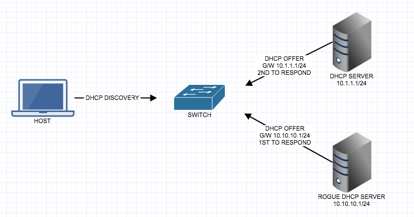
DHCP seems like a seemingly innocent, but common protocol, that can be used against our network. Since we know the DHCP discovery packet is a broadcast packet, just looking for a DHCP server and the host doesn’t care what DHCP server sends a DHCP OFFER back, it will accept the first offer, the DHCP offer includes information such as IP address, Subnet Mask, Default Gateway, DNS information. What if the first offer that is returned is a Rouge or Malicious DHCP server? Does that mean all traffic from that host using the Rogue DHCP servers gateway could be looking at all of the traffic passing through it? Yes! We can prevent this from happening with a feature called DHCP Snooping.

DHCP Snooping is going to snoop or listen into DHCP traffic to make sure that DHCP conversations go to the correct interface and allow that traffic to pass, otherwise it will be dropped. The interfaces to a known good DHCP server will be ‘trusted’ and all other interfaces will be untrusted, therefor the switch will know if DHCP conversations are happening on an untrusted interface then the traffic will be dropped and the interface will be put into err-disabled mode.

By default the switch considers all ports untrusted. We have to enable DHCP snooping globally, then trust at the interface level. IP ARP inspection and IP source-guard are dependent on DHCP snooping being enabled.

Enabled DHCP Snooping

tpw-sw1(config)#ip dhcp snooping


Enable DHCP Snooping on a VLAN

tpw-sw1(config)#ip dhcp snooping vlan 10


Trust Interface with DHCP server on it

tpw-sw1(config)#int gigabitEthernet 1/1

tpw-sw1(config-if)#ip dhcp snooping ?

  information  DHCP Snooping information

  limit        DHCP Snooping limit

  trust        DHCP Snooping trust config


tpw-sw1(config-if)#ip dhcp snooping trust


DHCP option 82

When packets come in on an untrusted port with option 82 set, those packets are not dropped. The switch will insert its own DHCP option 82 information (the switches MAC address), and when the packet is returned it will make sure its own DHCP option 82 information is in the reply if it is, it will remove its option 82 information and forward the packet normally, if not it will drop it.  This check is enabled by default.

Turn off the validity check

tpw-sw1(config)#no ip dhcp relay information check


Turn on Option 82

tpw-sw1(config)#ip dhcp snooping information option


Show Commands

tpw-sw1#sh ip dhcp snooping

Switch DHCP snooping is enabled

DHCP snooping is configured on following VLANs:

10

DHCP snooping is operational on following VLANs:

10

DHCP snooping is configured on the following L3 Interfaces:

Insertion of option 82 is enabled

Option 82 on untrusted port is not allowed

Verification of hwaddr field is enabled

Verification of giaddr field is enabled

DHCP snooping trust/rate is configured on the following Interfaces:


Interface                    Trusted    Relay Info policy     Rate limit (pps)

------------------------     -------    -----------------     ----------------

GigabitEthernet1/1        yes                               unlimited


Cisco : SPAN and Remote SPAN

As part of the CCNP Switch you get introduced to a topic called SPAN and Remote SPAN. This feature allows Network Engineers to capture packets flowing to and from a Interface or VLAN and mirror or forward those packets to a Packet Capture Analyzer software such as Wireshark.

Things to be aware of when setting SPAN and RSPAN up:

  • Make sure you destination port is of equivalent speed to the Source port otherwise you could drop packets.
  • A source port cannot be the same as a destination port
  • A destination port can only  be a part of one SPAN session
  • Source ports can be part of a EtherChannel but destinations ports cannot
  • Trunk ports can be setup as source and destination and the default behavior will monitor all active VLAN’s on that port
  • Destination Ports will not participate in STP, CDP, VTP, DTP or LACP
  • The number of SPAN sessions can vary on different switch models

The source can be set to entire VLAN’s (VSPAN) or individual ports. The Source is the port or VLAN you want to monitor.

Here is what the basic SPAN topology would look like:


Here is how to setup the Source SPAN interface.


tpw-sw1(config)#monitor session 1 source interface GigabitEthernet 1/1

The Destination is the port you have the network analyzer connected to.

tpw-sw1(config)#monitor session 1 destination interface GigabitEthernet 1/2

Verify your SPAN port setup.

tpw-sw1#show monitor

Session 1

---------

Type                   : Local Session

Source Ports           :

    Both               : Gi1/1

Destination Ports      : Gi1/2


The behavior is expected on a SPAN port:

tpw-sw1#sh int Gi1/1
FastEthernet1/1 is down, line protocol is down (monitoring)


However SPAN isn’t always going to be local, so luckily for us there is Remote SPAN (RSPAN). This feature allows the mirrored packets to traverse the trunk port to another switch via a separate VLAN. The configuration is fairly straightforward however there are a couple of caveats:

  1. All switches have to be RSPAN capable.
  2. VTP does treat the RSPAN VLAN like a regular VLAN and will propagate that through the VTP domain, but if its not you will have to add them manually to each switch
  3. VTP will prune the VLANS like a regular VLAN
  4. MAC address learning is disabled on the RSPAN VLAN
  5. Source and Destinations will be slightly different on each switch so don’t just copy the commands on each switch.

The topology would look something like this:


Here is the configuration for RSPAN tpw-sw1 – be  aware the destination RSPAN VLAN

tpw-sw1(config)#vlan 4000

tpw-sw1(config-vlan)#remote-span

tpw-sw1(config)#monitor session 1 source interface GigabitEthernet 1/1

tpw-sw1(config)#monitor session 1 destination remote vlan 4000

Verify your work.

tpw-sw1#show monitor

Session 1

---------

Type                   : Local Session

Source Ports           :

    Both               : Gi1/1

Dest RSPAN VLAN     : 4000

Here is the configuration for RSPAN tpw-sw2 – be aware the source is the RSPAN VLAN

tpw-sw2(config)#vlan 4000

tpw-sw2(config-vlan)#remote-span

tpw-sw2(config)#monitor session 1 source remote vlan 4000

tpw-sw2(config)#monitor session 1 destination interface GigabitEthernet 1/2

Verify your work.

tpw-sw2#show monitor

Session 1

---------

Type                   : Local Session

Source RSPAN VLAN        : 4000

Destination Ports     : Gi1/2


If you have a setup similar to below you have to name Remote SPAN VLAN 4000 on all intermediate switches.

Happy SPANNING 🙂


Cisco : Port Security

Is this frame from a trusted Source? That is the question!

As I continue my CCNP studies, I near the end of the CCNP Switch Course, this is a topic that was covered in the CCNA, and I haven’t really touched it since, so here is a refresher.

A port enabled with port security will expect to see frames sourced from a particular MAC address or group of MAC addresses, if the switch receives a frame from a MAC address it does not have listed the port takes action according to the violation mode that is set. The violation mode by default is to shutdown the port.

Enable Port Security

*You can only enable port security on a edge port, so that means that port can never become a trunk port*

tpw-sw1(conf)# int gi0/1
tpw-sw1(config-int)#switchport mode access
tpw-sw1(config-int)#switchport access vlan 10
tpw-sw1(config-int)#switchport port-security

Confirm it is working and information gathering

tpw-sw1# show port-security
tpw-sw1# show port-security address
tpw-sw1# show port-security interface gi0/1

More Port Security options

tpw-sw1(conf)# int gi0/1
tpw-sw1(config-int) switchport port-security ?
          aging - Port-security aging commands
          mac-address  - Secure mac address
          maximum - Max secure addresses
          violation - Security violation mode
tpw-sw1(config-int) switchport port-security maximum <1-6144>
tpw-sw1(config-int) switchport port-security violation ?
          protect - Security violation protect mode (drops the offending frames )
          restrict - Security violation restrict mode (drops, creates log messages, but port remains active )
          shutdown - Security violation shutdown mode (default will put the port into err-disabled (fix problem first and shut, no shut))
tpw-sw1(config-int) switchport port-security mac-address ?
         H.H.H - 48 bit mac address
         sticky - Configure dynamic secure addresses as sticky (dynamic addresses but kept on switch reload )
tpw-sw1(config-int) switchport port-security aging ?
         time Port-security aging time
         type Port-security aging type

This is just the very basics of Port Security, there is similar implementations on all switches I have worked with.