Palo Alto : Enable IPv6 and Create Default Route

To Enable IPv6 on the Firewall

Web GUI

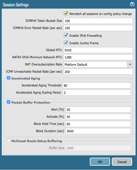
IPv6 firewalling is enabled under Device > Setup > Session:

*** You may have to restart your Firewall for IPv6 to be enabled.

On the CLI

> configure

# set deviceconfig setting session ipv6-firewalling [yes|no]

# commit

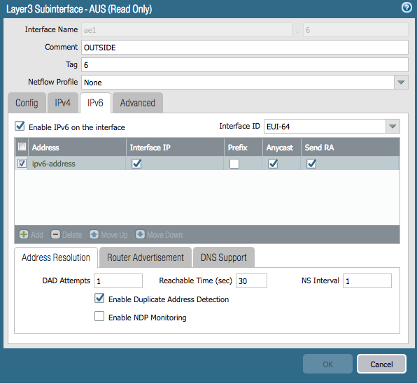
Here is the interface configuration I used:

Don’t forget to add a rule in your security policy that allows Your new IPv6 interface to talk to your Gateway.

Add Default Route

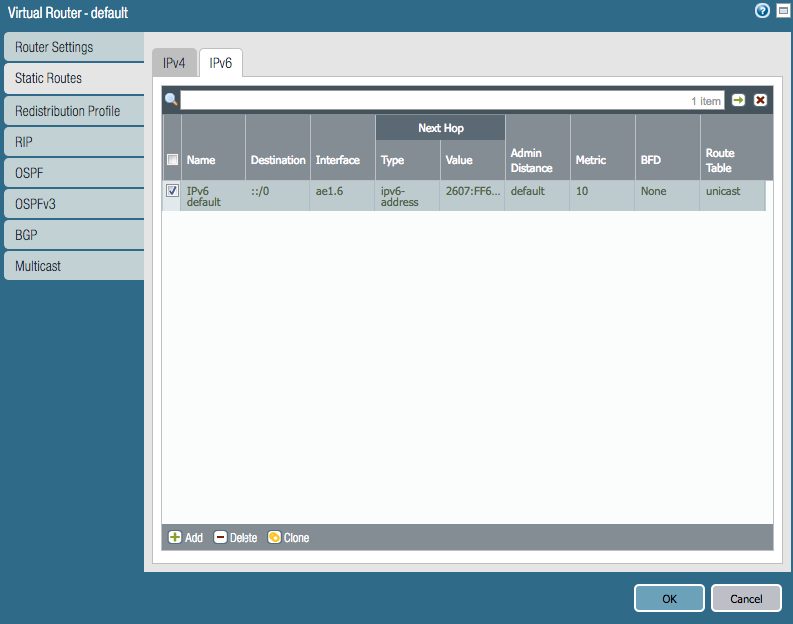
You will also have to add a default route under Network > Virtual Routers > Default > Static Routes > IPv6

The default route for IPv6 is ::/0 the next hop is the default gateway address

Network Utilities : SuperPutty Setup

I only use SuperPutty with GNS3, here is how.

  • GNS3 as of 1.5.2 doesn’t include the latest version so download it from here:
  • Start SuperPutty which will present you with the configuration options.  Set the following:
    • YOU MUST USE THE PUTTY PROVIDED WITH GNS3.  If you don’t, you’ll receive errors “unknown option -wt” when opening consoles with SuperPutty from GNS3
    • putty.exe location (Required): C:\Program Files\GNS3\putty.exe
      • Or where-ever GNS3 is installed
    • Click the “Advanced: tab > Check off “Only allow single instance of SuperPutty to run”
  • Set the other options however you like
  • Open up Preferences in GNS3 > General > Console applications tab
  • Change the console application for telnet and serial to use SuperPutty
  • If you want to use keep the same color scheme that is used by the regular Putty console, add “-gns3 5 -skin 4” at the end i.e.
    • c:\dropbox\apps\superputty\SuperPutty.exe -telnet “%h -P %p -wt \”%d\” -gns3 5 -skin 4″

GNS3 : Install and Configure

This install is intended for running IOU/IOL images on the GNS3 VM because it is the preferable way of running IOS in GNS3 now.

Pre-Requisites:

  1. Install VMware Workstation Player
    http://www.vmware.com/products/player/playerpro-evaluation.html
  2. Install VMware VIX API
    https://www.vmware.com/support/developer/vix-api/
  3. Install Wireshark
    https://www.wireshark.org/download.html
    Install WinPCAP provided by Wireshark


Install GNS3:

  1. Install GNS3
    https://www.gns3.com/software/download
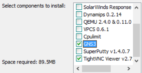
  2. Install only the following components:

  1. We don’t need Dynamips/QEMU/VPCS/Cpulimit because we’ll be running everything off of the GNS3 VM server.  We don’t install SuperPutty from here because its not the latest version and the first thing it does when you open it is bug you about upgrading to the latest version.  There are setup instructions for it below.

Install Loopback Adapter

  1. Open an Admin Command Prompt

cd “c:\Program Files\gns3”

loopback-manager.cmd

  1. Install a new Loopback interface (reboot required)
  2. Reboot
  1. Rename the new Loopback adapter to “Loopback”
  2. Assign it an IP address


Setup GNS3 VM:

  1. Download the GNS3 VM version that matches the installed GNS3 version
    https://github.com/GNS3/gns3-gui/releases
  2. Import the VM and keep the defaults
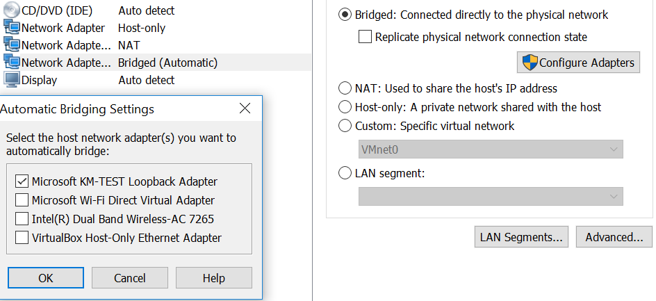
  3. Add a 3rd Network Adapter that will be in Bridged mode and connected to the Loopback adapter (Microsoft KM-TEST Loopback Adapter)

  1. Power on the VM
  2. SSH into the VM using gns3/gns3 for the credentials
    1. Sudo to root and run the following:
      1. echo ‘127.0.0.127 xml.cisco.com’ >> /etc/hosts
  3. Leave the VM powered on, we’re done with it for now
  4. Open an Administrator command prompt
  5. cd into the GNS3 install directory and run the following:
    1. IMPORTANT: On my work laptop, added the additional interfaces broke network connectivity to the VM after they were added.  I have no idea why but after I reinstalled VMware Workstation which uninstalled all the adapters, I was able to connect to the VM again.  On the work laptop, I’m running without the additional adapters and it seems fine so far.
    2. vmnet-manager.cmd
    3. Select option 1 which will add the vmnet interface 2 to 19 (this can take a while, please be patient)
    4. If it looks like this process has hung, you follow step 2 in the url below to add the adapters
      https://www.gns3.com/support/docs/how-to-use-vmware-player-in-gns3


Configure GNS3 to use the GNS3 VM server:

  1. Open up GNS3
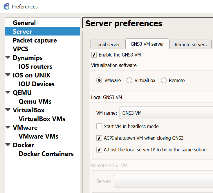
  2. Goto Edit > Preferences

    Be sure to leave “Start VM in headless mode” unchecked.  I ran into issues where the VM would not automatically startup when opening GNS3 and also cause the GNS3 process to linger when closing out of it.
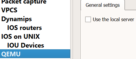
  3. Disable “Use of the local server” for Dynamips and QEMU.  We’ll use the GNS3 VM instead for running those processes.

Packet capture VPCS Dynamips IOS routers General settings Use the local server Path to Dynamips:


Create the L2/L3 IOU Devices:

  1. Goto Edit > Preferences
  2. Set the iourc file to use with the license (IOU devices need a license to run)
  3. Create the L2 image:
  4. Create the L3 image:

Add Device Image

New appliance template > Add and IOU > Run the IOU > New Image > Browse


i86bi-linux-l2-ipbasek9-15.1e.bin – IOU-L2

i86bi-linux-l3-adventerprisek9-15.4.2T.bin – IOU-L3


Operational Notes:

  • Sometimes a restart of all the routers/switches are required when new links are created between devices.  Even though the line protocols show as up, I’ve found a restart is required for traffic to actually pass through them.


If you want to use SuperPutty as the SSH client for GNS3 click this link:
SuperPutty with GNS3

The Packet Wizard : First Ever Fan Mail

Yesterday I received my first ever fan mail. I am grateful the blog is proving useful to some, and as my content grows hopefully the usefulness of the blog also grows. If anyone want to send me mail or anything else I am open to that. I accept : IOU’s, Gift Cards, Cash, Precious Gems, Hugs, and IT equipment. In all honesty I am over the moon its helping someone.

Open Gear : Basic Commands

Here are some basic commands to help you get around when using Open Gear Terminal Server. These devices are incredibly useful for accessing Network Devices Out of Band. On the newer models you can use them with Cellular Access and a Static IP, so when your Device or Network goes down you can still access your devices Out of Band. 

To view all ports

pmshell

To exit from one device

~. <Enter>

$ pmshell

(standard user)

or

# pmshell

(root user)


For example, enter a device to be managed:

2: CISCOASA   3: CISCOSWITCH   4: CISCOROUTER

> 3

Once the selection has been made, type one of the following selections:

CISCOASA> ~?  (Note: Typing this ESCAPE sequence should not be visible for this to work. Should you start to see typing, hit enter 1-2 times to refresh)

Help Menu: ~~?     —>  double tilde is required for ALL OpenSSH based terminals (Mac & Linux)

Shell Commands:

~b – Generate BREAK

~h – View history

~p – Power menu

~m – Connect to port menu

~. – Exit pmshell

~? – Show this message


PMSHELL Command Breakdown:

~b –> (BREAK sequence) often used in device recovery situations.

~h –> recent port history of RX/TX operations

~p –> (optional) if a managed PDU has been configured, the device would have the ability to pull-up the power menu directly from the device.

~m –> at any point when connected to an active console session, this will return you back to the main pmshell selection menu.

~. –> (tilde period)  exit the pmshell system when actively connected to a console session.

~? –> displays pmshell command usage information.

Cisco : Serial Numbers

Today I have spent some time trying to find serial numbers on multiple Cisco devices, some Routers, Switches, Firewalls and Wireless LAN Controllers. Here is 7 ways I have found:

  1. Locate the serial number tag on the device chassis.
  2. The serial number is displayed in the banner during boot.
  3. “show version” command. (Look for Processor board ID or S/N)
  4. “show inventory” command. (Look for Hw Serial# or SN:)(Also works on WLC’s)
  5. “show diag” command. (Look for Chassis Serial Number)
  6. “show hardware” command. (Look for Processor board ID or S/N)
  7. “show tech-support” command. 

SecureCRT : Logging

Logging your session when doing any kind of network work is very important and can save your ass. It has saved mines on multiple occasions. One reason is it allows you to look back and see what you may have done wrong, so you can troubleshoot a issue more effectively. Other reasons are it give you the user a quick way to backup a device if you show the configuration file when working on it. I make it a habit of showing the configuration file before I do any work, so I always have a back out strategy incase something goes wrong.

SecureCRT Logging

Options > Edit Session Defaults

File path to where you are storing your logs /Logs/%M-%D-%Y/%S (%H) — %h-%m.log

Start Log Upon Connect

Append to File

Start recording S (%H) – %h:%m:%s

Stop recording S (%H) – %h:%m:%s

Happy Logging!

Cisco/Brocade : Basic Similar Commands

  • Here are some basic switch commands and the Cisco to Brocade differences, even though the OS’s are similar they have some subtle differences.

Task

Cisco

Brocade

Configure a VLAN

Interface vlan 2

Vlan 2

Configure a trunk port

Int fa0/1

Switchport trunk encap dot1q

Switchport mode trunk

Vlan 2

Tagged eth 0/1/1

Vlan 3

Tagged eth 0/1/1

Vlan 4

Tagged eth 0/1/1

Interface ethernet 0/1/1

Dual-mode 1

Configure a access port

Int fa0/1

Switchport access vlan 2

Vlan 2

Untagged eth 0/0/1

Configure an IP address on a VLAN

Int vlan2

Ip address 192.168.1.1 255.255.255.0

Vlan 2

Router interface ve 1

Interface ve1

Ip address 192.168.1.1 255.255.255.0

Configure a range of ports

Int range fa0/1-10

Int eth 0/1/1 to 0/1/5

Configure a port for both voice and data vlans

Int fa0/1

Switchport access vlan2

Switchport voice vlan3

vlan2

Tagged eth 0/1/1

vlan3

Tagged eth 0/1/1

Inter eth 0/1/1

Dual-mode 1

Voice-vlan 3

Inline power

Show the interface status of a port/vlan

Sh int fa0/1

Show int eth 0/1/1

See CDP Neighbors

Show cdp neighbors

Show fdp neighbors

Ruckus/Brocade : Configure Spanning Tree 802.1w/RSTP

I want to point out that Ruckus/Brocade has 2 commands that contradict each other when configuring Spanning Tree:

Brocade(config-vlan-1)#spanning-tree  ?

  802-1w          Enable Rapid Spanning Tree IEEE 802.1w
  rstp                  Enable Rapid Spanning Tree

Since RSTP is the same as 802.1w further clarification is needed.

Brocade(config-vlan-1)#spanning-tree rstp  is a Brocade early implementation of the IEEE 802.1W which provided only a subset of the standard, whereas the

Brocade(config-vlan-1)#spanning-tree  802-1w feature provides the full standard, so basically you should use 802.1w.

How to configure Spanning Tree on Brocade

Ran mainly on a per VLAN basis.

Brocade# conf t
Brocade (config)#vlan 1
Brocade (config-vlan-1)#  spanning-tree 802-1w – enabled spanning tree basic mode
Brocade (config-vlan-1)# show 802-1w – shows spanning tree information
Brocade (config-vlan-1)# spanning-tree 802-1w priority 0 – to designate that switch Root bridge

If you know there is a point to point link between 2 rapid spanning tree devices you have to turn that on at the interface level

Point-to-Point/Uplinks
Brocade (config-vlan-1)#int e 1/1/1
Brocade (config-if-e10000-1/1/1)# spanning-tree 802-1w admin-p2pt-mac – don’t allow for a broadcast domain, assume there is a link between 2 rapid spanning tree root bridges/uplinks ( without this it will fail over in 2 seconds or less, but fail back takes the traditional 30 of listening and learning, but this allows it to fail forward and back in 2 seconds or less

Access/Edge-Ports
Brocade (config-if-e10000-1/1/1)# int e 1/1/3 to 1/1/24

Brocade (config-if-e10000-1/1/3-1/1/24)#  spanning-tree 802-1w admin-edge-port (not really required, just means topology changes on the edge is not going to cause re-convergence on the core links or vice versa

Brocade (config-if-e10000-1/1/3-1/1/24)#  show run – will see spanning tree on the VLAN and the int ports

***DO NOT USE VLAN1 IN PRODUCTION, THIS IS PURELY FOR DEMONSTRATION PURPOSES***