Arista : VARP Configuration

Virtual-ARP or VARP is a routing technique that allows multiple switches or routers to simultaneously route packets from a common Virtual IP (VIP) address in an active/active switch/router configuration. Each switch or router is configured with the same VIP address on the corresponding VLAN interfaces (SVI) and a common virtual MAC address. In MLAG topologies, VARP is preferred over VRRP because VARP does not require traffic to traverse the peer-link to the master router as VRRP would.

A maximum of 500 VIP addresses can be assigned to a single VLAN interface. All virtual addresses on all VLAN interfaces resolve to the same virtual MAC address. However you cannot have a secondary VIP on the same VLAN interface, you can however implement VRRP on the same VLAN interface as VARP.

VARP functions by having each switch respond to ARP and GARP requests for the configured router IP address with the virtual MAC address. The virtual MAC address is only for inbound packets and never used in the source field of outbound packets.

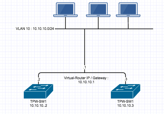
The following commands configures 10.10.10.1 as the virtual IP address for VLAN 10. The Virtual-Router MAC address is entirely invented by you, I had a real issue finding clarification that it was just a made up MAC address, so here is my invented made up Virtual-Router MAC 1010.1010.1010 as the virtual MAC address on both switches. I also ran into an issue where #ip routing had to be enabled.

Here is what the Topology would look like:

Configuration that implements VARP on the first switch

TPW-SW1(config)#ip virtual-router mac-address 1010.1010.1010

TPW-SW1(config)#interface vlan 10

TPW-SW1(config-if-vl10)#ip address 10.10.10.2/24

TPW-SW1(config-if-vl10)#ip virtual-router address 10.10.10.1

Configuration that implements VARP on the second switch

TPW-SW2(config)#ip virtual-router mac-address 1010.1010.1010

TPW-SW2(config)#interface vlan 10

TPW-SW2(config-if-vl10)#ip address 10.10.10.3/24

TPW-SW2(config-if-vl10)#ip virtual-router address 10.10.10.1


The Packet Wizard : Work Travel

I am home! I have been travelling for work for the best part of the past 5 weeks. I was in Boston doing a network refresh the week before Easter, which included replacing all the network cables, installing new Palo Alto Firewalls and removing Cisco ASA’s. I also removed all Cisco Switches and installed a new stack of Ruckus 7250, replace the core switches with 2 new Arista’s. I then came home for 2 days and I left again for Singapore for 3 weeks. I was in Singapore integrating a new company we bought into our network, this was a team effort as we had other sites to bring online within 48 hours. Copenhagen and a small site in Kaohsiung, Taiwan. I have learned a lot over the past 2 month. I have some articles to write on what I have learned but for now, I just wanted to give a quick update. Here is some cable porn from the Boston Network Refresh.

Before:

After:


Arista : MLAG Setup


Notice: Trying to access array offset on value of type null in /home/minted6/thepacketwizard.com/wp-content/plugins/amazon-associates-link-builder/vendor/mustache/mustache/src/Mustache/Parser.php on line 278

I have recently been setting up some Arista switches for a network refresh at our Boston site.

MLAG is short for Multi Chassis Link Aggregation and it allows more than 1 switch usually 2, to act like one logical switch which can allow you to just manage one switch instead of multiple. It also helps with redundancy and diversify paths. Its an awesome technology.  Here is the basic MLAG Topology:

1. Create Port Channel For Peer Links

I am using 2 Arista DCS-7150S-24-R switches with 2 10Gb Ethernet as our MLAG peer links. On each switch we will create a port channel 1000

 tpwsw1# config t
 tpwsw1(conf)#interface e23-24
 tpwsw1(config-if-Et23-24)# channel-group 1000 mode active
 tpwsw1(config-if-Et23-24)# interface port-channel 1000
 tpwsw1(config-if-Po1000)# switchport mode trunk


2. Create a VLAN for Peer MLAG Communication

You need to create a separate VLAN for MLAG communication and assign it the mlag-peer trunk group and disable spanning-tree on the VLAN. This step is done on both switches.

 tpwsw1(conf)#vlan 4094
 tpwsw1(config-vlan-4094)# trunk group mlag-peer
 tpwsw1(config-vlan-4094)# interface port-channel 1000
 tpwsw1(config-if-Po1000)# switchport trunk group mlag-peer
 tpwsw1(config-if-Po1000)# exit
 tpwsw1(conf)#no spanning-tree vlan 4094


 tpwsw2(conf)#vlan 4094
 tpwsw2(config-vlan-4094)# trunk group mlag-peer
 tpwsw2(config-vlan-4094)# interface port-channel 1000
 tpwsw2(config-if-Po1000)# switchport trunk group mlag-peer
 tpwsw2(config-if-Po1000)# exit
 tpwsw2(conf)#no spanning-tree vlan 4094


3. Set an IP on each Switch
On VLAN 4094 that was created above, we need to assign it an IP so each switch can communicate over layer 3 with each other.


tpwsw1(conf)#int vlan 4094
tpwsw1(config-if-Vl4094)# ip address 1.1.1.1/30


tpwsw2(conf)#int vlan 4094
tpwsw2(config-if-Vl4094)# ip address 1.1.1.2/30

***Send some pings to confirm basic connectivity


4. Configure MLAG peering for each switch

 tpwsw1(config)#mlag
 tpwsw1(config-mlag)#local-interface vlan 4094
 tpwsw1(config-mlag)#peer-address 1.1.1.2
 tpwsw1(config-mlag)#peer-link port-channel 1000
 tpwsw1(config-mlag)#domain-id mlagDOMAIN


 tpwsw2(config)#mlag
 tpwsw2(config-mlag)#local-interface vlan 4094
 tpwsw2(config-mlag)#peer-address 1.1.1.1
 tpwsw2(config-mlag)#peer-link port-channel 1000
 tpwsw2(config-mlag)#domain-id mlagDOMAIN


5. Verify MLAG Domain
On each switch, do a #show mlag to see if MLAG is up and running and you can confirm this by seeing State:Active and peer-link status: UP and locl-int status:UP

tpwsw1(config-mlag)#show mlag
MLAG Configuration:
domain-id : mlagDOMAIN
local-interface : Vlan4094
peer-address : 1.1.1.2
peer-link : Port-Channel1000
MLAG Status:
state : Active
negotiation status : Connected
peer-link status : Up
local-int status : Up
system-id : 02:1c:73:1e:97:dc
MLAG Ports:
Disabled : 0
Configured : 0
Inactive : 0
Active-partial : 0
Active-full : 0


tpwsw2(config-mlag)#show mlag
MLAG Configuration:
domain-id : mlagDOMAIN
local-interface : Vlan4094
peer-address : 1.1.1.1
peer-link : Port-Channel1000
MLAG Status:
state : Active
negotiation status : Connected
peer-link status : Up
local-int status : Up
system-id : 02:1c:73:1e:97:dc
MLAG Ports:
Disabled : 0
Configured : 0
Inactive : 0
Active-partial : 0
Active-full : 0


You can read more about MLAG here – https://www.arista.com/en/products/multi-chassis-link-aggregation-mlag

A great book to read about Arista is called Arista Warrior. I loved it. You can buy it here: