Ruckus : L3 Routing Image on Switch

There are 2 different versions of code for the ICX switches depending on what you are doing with them. Layer 3 or Layer 2. If you are going to be doing L3, you will need a license for that.

Software on the device is listed within:


 #show flash


SPS – S is for Switching

SPR – R is for Routing

Ruckus Recommend if you are using L3 then to boot the system to SPR.

Once it has rebooted do not forget to make sure you set it to boot from the Router image if the switch was to reboot for any reason. (make sure you are in configure terminal mode or you will cause a reboot)

Avoid this!!!

This is correct in (config) mode

Ruckus : Licensing with TFTP & USB

This topic in my opinion is one of the really big downfalls of the Ruckus Switches and there are a couple, but I will leave that for another time. Licensing however, It is overly complicated, and a total waste of time. Why when you buy a piece of hardware it doesn’t come working the way you want it to, is beyond me. Ruckus have to fix this or they will lose customers. They recently told me that they had delivered 42 ICX switches to a customer. When I thought about the licensing process that needs to be done on each device, I think I would have quit on the spot. Luckily…I only had to license 4…for now. This however is not normal practice,  Here Goes:

When you buy a license key wether it be for Layer 3 or 10G ports you need a transaction key and then you need a License ID.

To get the LicenceID you need to run the command:

#show version

The you need to go to https://support.ruckuswireless.com/code_registration (you will need a ruckus account for this). The License Code comes in a separate Email (if you don’t receive that you may need to contact support). Follow the steps online:


They then have you download a file or they will send you a xml file.
(I recommend opening up the XML file and naming them something better than what they send you).

For USB Install

Copy the XML License Files to USB Stick

View Current License

#Show license

View License files on USB on Switch

# show files disk0

Copy license files from USB to Switch

#Copy disk0 license <license-filename> unit <switch-number>

For TFTP Install

Copy files from TFTP Server to Switch

#copy tftp license <tftp-server-ip> <license-filename> unit <switch-number>

Delete License

#Licence delete unit <switch number>

Verify License

#show license

Ruckus : ICX Add Unit to Existing Stack

Continuing my theme from last week with the Ruckus ICX Switches. Here is how to add a switch to a stack hot.

Show existing Stack

#Stack secure-setup

Which will discover the new device. Election will run and reboot the newly Stacked Units.

#show stack

‘Wr mem’ on the master switch


Ruckus : ICX Initial Stacking Configuration


Notice: Trying to access array offset on value of type null in /home/minted6/thepacketwizard.com/wp-content/plugins/amazon-associates-link-builder/vendor/mustache/mustache/src/Mustache/Parser.php on line 278

As you may know Brocade ICX switching line was purchased by Ruckus Networks. I have been messing with the Ruckus ICX 7250. Here is the steps to stack them using their Twin-AX cables.

Firstly stacking ICX switches has to be done on 10G Ports, so firstly you have to verify you have the correct license for those ports with the command:

# show license

As you can see from the output there 2 licensed 10G ports and that is the minimum you need to stack.

Doing a ‘show run’ confirms that 1/2/1 and 1/2/3 are set to 10G because they DO NOT show up in show run.


Once the 10G ports have been confirmed you can stack them. Here is how.

I have included a link where you can see the cost or purchase these devices:

Here is a picture of a Twin-AX Cable

I have included a link where you can see the cost or purchase these devices:

Once the Cables are connected you only have to enable stacking on one switch

Now search for the other devices connected to the stack and confirm you want them part of the election process, then all the non master switches will reboot.

Once the members have rebooted you can verify the stack us up and also shows the connections between the stack ports

Don’t forget to Save

#wr mem


Cisco : Enable SSH on Cisco Switch, Router and ASA

When you configure a Cisco device, you need to use a console cable and connect directly to the system to access it. Follow the SSH setup below, will enable SSH access to your Cisco devices, since SSH is not enabled by default. Once you enable SSH, you can then access it remotely using SecureCRT or any other SSH client.

Set hostname and domain-name

The hostname has to have a hostname and domain-name.

switch# config t
switch(config)# hostname tpw-switch
tpw-switch(config)# ip domain-name thepacketwizard.com

Setup Management IP

In the following example, the management ip address will be set to 10.100.101.2 in the 101 VLAN. The default gateway points to the firewall, which is 10.100.101.1

tpw-switch# ip default-gateway 10.100.101.1
tpw-switch# interface vlan 101
tpw-switch(config-if)# ip address 10.100.101.2 255.255.255.0

Generate the RSA Keys

The switch or router should have RSA keys that it will use during the SSH process. So, generate these using crypto command as shown below.

tpw-switch(config)# crypto key generate rsa
  The name for the keys will be: tpw-switch.thepacketwizard.com
  Choose the size of the key modulus in the range of 360 to 2048 for your
    General Purpose Keys. Choosing a key modulus greater than 512 may take
    a few minutes.

How many bits in the modulus [512]: 1024
  % Generating 1024 bit RSA keys, keys will be non-exportable...[OK]

Setup the Line VTY configurations

Setup the following line vty configuration, where input transport is set to SSH only. Set the login to local, and password to 7, and make sure Telnet is not enabled:

tpw-switch# line vty 0 4
 tpw-switch(config-line)# transport input ssh
 tpw-switch(config-line)# login local
 tpw-switch(config-line)# password 7
 tpw-switch(config-line)# exit

If you have not set the console line yet, use the following:

tpw-switch# line console 0
tpw-switch(config-line)# logging synchronous
tpw-switch(config-line)# login local

Create the username password

If you don’t have an username created already, here is how:

tpw-switch# config t
Enter configuration commands, one per line.  End with CNTL/Z.
tpw-switch(config)# username thepacketwizard password tpwpassword123
tpw-switch# enable secret tpwenablepassword

Make sure the password-encryption service is turned-on, which will encrypt the password, and when you do “show run”, you’ll see only the encrypted password and not clear-text password.

tpw-switch# service password-encryption

Verify SSH access

From the switch, if you do ‘show ip ssh’, it will confirm that the SSH is enabled on this Cisco device.

tpw-switch# show ip ssh
 SSH Enabled - version 1.99
 Authentication timeout: 120 secs; Authentication retries: 3

After the above configurations, login from a remote machine to verify that you can ssh to this cisco switch.

In the example, 10.100.101.2 is the management ip-address of the switch.

TPW-Remote-Computer# ssh 10.100.101.2
 login as: thepacketwizard
 Using keyboard-interactive authentication.
 Password:

tpw-switch>en
 Password:
 tpw-switch#

You are now setup and logged in on SSH!

To read more on SSH visit: https://en.wikipedia.org/wiki/Secure_Shell

Palo Alto : Upgrade High Availability (HA) Pair

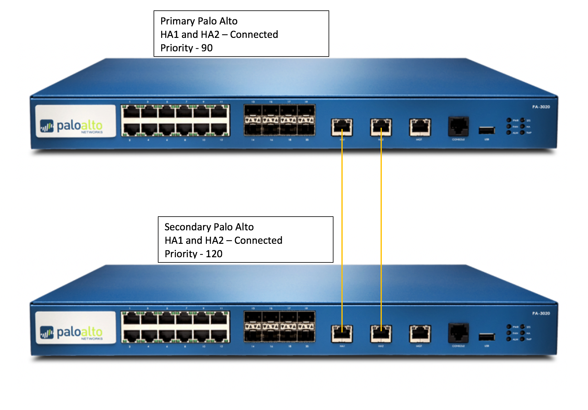
Over the last 3 weeks since the Christmas and New Year Holidays,  I have been upgrading all of our firewalls globally, many of them are an High Availability Pair. This means they are redundant and being redundant allows me to upgrade them individually while the site stays full up and functional.

The  instructions for upgrading an HA pair are recommended because:

      • It verifies HA functionality before starting the upgrade.
      • It ensures the upgrade is successfully applied to the first device before starting the upgrade on the second.
      • At any point in the procedure, if any issue arises, the upgrade can be seamlessly reverted without any expected downtime (unless you are having any dynamic routing protocols line OSPF/BGP).
      • When finished, the final active/passive device state will be the same as it was before the upgrade with the fewest number of fail overs possible (2).

Before you Begin :

Take backup of the configuration as well as Tech Support from both HA Peers. Give proper names to each file, here is how:

Device > Setup > Operations > Save Named Configuration Snapshot

Device > Setup > Operations > Export Named configuration Snapshot

Device > Setup > Operations > Export Device State (If device managed from panorama

Device > Support > Generate Tech Support File, and then download it. (Might be required if any issues)

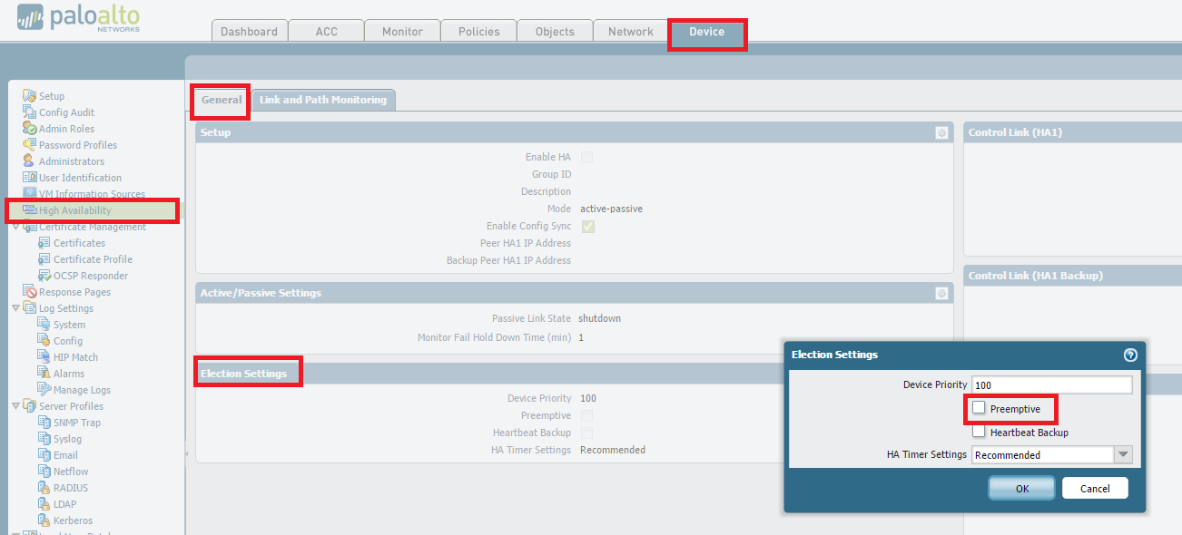
(Optional but recommended) Disable preemption on High Availability settings to avoid the possibility of unwanted failovers. Disabling preempt configuration change must be committed on both peers. Likewise, once completed, re-enabling must be committed on both peers.

To disable preempt, go to

Device > High Availability > Election Settings and uncheck Preemptive.
Then, perform a commit.


If upgrade is between major versions (4.1 -> 5.0 OR 5.0-> 6.0), it is advisable to disable TCP-Reject-Non-SYN, so that sessions can failover even when they are not in sync. : Do this on both Firewalls from the CLI:

 # set deviceconfig setting session tcp-reject-non-syn no
 # commit


(Optional but recommended) Arrange for Out-of-Band access (Console access) to the firewall if possible. This is again to help recover from any unexpected situation where we are unable to login to the firewall. If you have a Terminal Server awesome, if not a simple Cell Phone tethered to a Laptop with RDP is also fine.


The Upgrade Process

Suspend Backup Device 

From the CLI

 > request high-availability state suspend

From the GUI

Go to Device > High Availability > Operational Commands  > Suspend local device

Install the new PAN-OS on the suspended device

Device > Software > Install

Reboot the device to complete the install.

When the upgraded device is rebooted, check the dashboard to check the version, wait for all the interfaces to come backup green.

If the device is still in suspended state make it functional again

From the CLI

> request high-availability state functional

From the GUI

Go to Device > High Availability > Operational Commands  > Make Local Device Functional


Repeat steps on other firewall.


Suspend Primary Device

From CLI

> request high-availability state suspend

From the GUI

Go to Device > High Availability > Operational Commands  > Suspend local device.


*The Backup Firewall will become Active – it does take 30-45 seconds so don’t panic


Install the new PAN-OS on the suspended device:

Device > Software > Install

Reboot the device to complete the install.

When the upgraded device is rebooted, check the dashboard to check the version, wait for all the interfaces to come backup green.

If the device is still in suspended state make it functional again

From the CLI

> request high-availability state functional

From the GUI

Go to Device > High Availability > Operational Commands  > Make Local Device Functional

To Get Primary Back to Primary by suspending the backup (current active) firewall (The Original Backup Firewall)

From the GUI,

Go to Device > High Availability > Operational Commands  > Suspend local device.

Once the Primary became active again, enable the suspended backup firewall

Enable TCP-Reject-Non-SYN, so that sessions can failover even when they are not in sync. : (Do this on both Firewalls)

# set deviceconfig setting session tcp-reject-non-syn yes
# commit


Re-Enable preempt configuration change must be committed on both peers. To re-enable preempt, go to Device > High Availability > Election Settings and uncheck Preemptive.  Then, perform a commit.


How to Downgrade

If an issue occurs on the new version and a downgrade is necessary:

To revert to the previous PAN-OS screen, run the following CLI command:

# debug swm revert

This causes the firewall to boot from the partition in use prior to the upgrade. Nothing will be uninstalled and no configuration change will be made.


However please be aware while running this command –

After rebooting from a SWM revert, the configuration active at the time before upgrade will be loaded with the activation of the previous partion. Any configuration changes made after upgrade will not be accounted for and will need to be manually recovered by loading the latest configuration version and committing the changes.

General Troubleshooting : How to determine the proper MTU size with ICMP pings

How to determine the proper MTU size with ICMP pings

To find the proper MTU size, you have to run a special ping to the destination address. This is usually the gateway, local server or an IP address domain name internet (e.g. thepacketwizard.com). You probably want to start around 1800 and move down 10 each time until you get to a ping reply. Once you have a ping reply start moving backup by 2-5 bits to get to the fragmented packet size. Take that value and add 28 to the value to account for the various TCP/IP headers. E.g. let’s say that 1452 was the proper packet size (where you first got an ICMP reply to your ping). The actual MTU size would be 1480, which is the optimum for the network we’re working with. Header size varies depending what the packet is traversing.


1500 Standard MTU

– 20 IP Header

– 24 GRE Encaps.

– 52 IPSec Encap.

– 8 PPPoE

– 20 TCP Header


Windows

ping  (host) (-f) (-l (packet size))

An example would be:

ping  thepacketwizard.com -f -l 1800

(result = "Packet needs to be fragmented but DF set.")

ping thepacketwizard.com -f -l 1472 

(result = reply)


The options used are:

      • -f: set “Don’t Fragment” flag in packet
      • -l size: send buffer size


Linux

ping (-M do) (-s (packet size)) (host)

An example would be:

ping thepacketwizard.com -M do -s 1800

(result = "Frag needed and DF set" or "message too long")

ping thepacketwizard.com -M do -s 1472

(result = reply)


The options used are:

      • -M <hint>: Select Path MTU Discovery strategy. <hint> may be either “do” (prohibit fragmentation, even local one), “want” (do PMTU discovery, fragment locally when packet size is large), or “dont” (do not set DF flag).
      • -s packetsize: Specifies the number of data bytes to be sent. The default is 56, which translates into 64 ICMP data bytes when combined with the 8 bytes of ICMP header data.


Mac

ping (-D) (-s (packet size)) (host)

An example would be:

ping thepacketwizard.com -D -s 1800

(result = "sendto: Message too long")

ping thepacketwizard.com -D -s 1462

(result = reply)


The options used are:

      • -D: set the “Don’t Fragment” bit
      • -s packetsize: Specify the number of data bytes to be sent. The default is 56, which translates into 64 ICMP data bytes when combined with the 8 bytes of ICMP header data.

There is a lot to know about MTU check it out on Wikipedia : Wikipedia – MTU

Palo Alto : Reconnaissance Protection Whitelist

Recently I have been implementing a software called Insight VM by Rapid 7 which runs reconnaissance on our network looking for vulnerabilities. Whilst this software is scanning, I was finding the Firewall would block it (like its supposed to) and then complain like crazy that it and its Network was being targeted. 27,000 email over night I decided to research how to solve this issue. Luckily Palo Alto have thought about this.

Here is how to implement Reconnaissance Protection Whitelist:

Select Network>Network Profiles>Zone Protection>Reconnaissance Protection to add a source address exclusion whitelist to your zone protection Profile.

Add an address to your source address exclusion whitelist. You add up to 20 IP addresses or netmask address objects.