Cisco Route : PPP

By default Cisco uses HDLC encapsulation on Serial interfaces. We are going to setup a simple PPP link with Authentication.

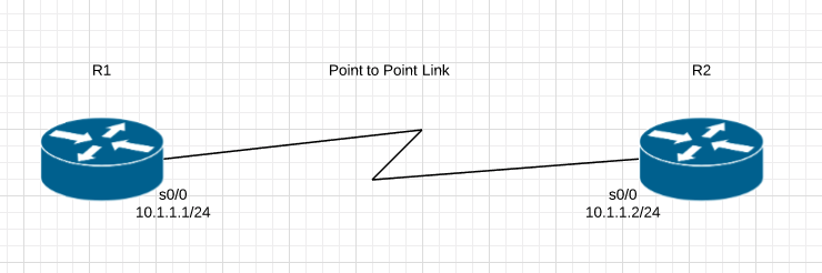
R1#show int serial 0/0   

Serial0/0 is up, line protocol is up

  Hardware is GT96K Serial

  Internet address is 10.1.1.1/24

  MTU 1500 bytes, BW 1544 Kbit/sec, DLY 20000 usec,

     reliability 255/255, txload 1/255, rxload 1/255

  Encapsulation HDLC, loopback not set

  Keepalive set (10 sec)

  Last input 00:00:09, output 00:00:07, output hang never

  Last clearing of "show interface" counters never

  Input queue: 0/75/0/0 (size/max/drops/flushes); Total output drops: 0

  Queueing strategy: weighted fair
R2#show int serial 0/0

Serial0/0 is up, line protocol is up

  Hardware is GT96K Serial

  Internet address is 10.1.1.2/24

  MTU 1500 bytes, BW 1544 Kbit/sec, DLY 20000 usec,

     reliability 255/255, txload 1/255, rxload 1/255

  Encapsulation HDLC, loopback not set

  Keepalive set (10 sec)

  Last input 00:00:05, output 00:00:06, output hang never

  Last clearing of "show interface" counters never

  Input queue: 0/75/0/0 (size/max/drops/flushes); Total output drops: 0

  Queueing strategy: weighted fair

We have to change that to PPP encapsulation on both sides, other wise there will be a encapsulation mismatch and the Interface will remain up but the line protocol will be down.

R1(config-if)#encapsulation ?

  frame-relay  Frame Relay networks

  hdlc         Serial HDLC synchronous

  lapb         LAPB (X.25 Level 2)

  ppp          Point-to-Point protocol

  smds         Switched Megabit Data Service (SMDS)

  x25          X.25
R1(config-if)#encapsulation ppp
R1(config-if)#

*Mar  1 00:05:27.739: %LINEPROTO-5-UPDOWN: Line protocol on Interface Serial0/0, changed state to down

R1(config-if)#exit                             

R1(config)#exit

R1#sh int serial 0/0

Serial0/0 is up, line protocol is down 

  Hardware is GT96K Serial

  Internet address is 10.1.1.1/24

  MTU 1500 bytes, BW 1544 Kbit/sec, DLY 20000 usec,

     reliability 255/255, txload 1/255, rxload 1/255

  Encapsulation PPP, LCP Listen, loopback not set
R2(config)#int serial 0/0

R2(config-if)#encapsulation ppp

R2(config-if)#exit

R2(config)#exit

R2#sh int serial 0/0

Serial0/0 is up, line protocol is up 

  Hardware is GT96K Serial

  Internet address is 10.1.1.2/24

  MTU 1500 bytes, BW 1544 Kbit/sec, DLY 20000 usec,

     reliability 255/255, txload 1/255, rxload 1/255

  Encapsulation PPP, LCP Open

We should move from HDLC to PPP because PPP has some features that HDLC doesn’t for example, Authentication options, error detection and error recovery features.

Password Authentication Protocol (PAP)  and  Challenge Authentication Protocol (CHAP)

PAP is very passive authentication, where as CHAP actively asks who are you?

PAP also sends username and password in Clear Text.

Here is how to configure CHAP on both routers

The username is the Hostname of the Peer Router you are authenticating to. The passwords must match.

R1(config)#username R2 password TPW

R1(config)#int serial 0/0

R1(config-if)#ppp authentication chap


R2(config)#username R1 password TPW

R2(config)#int serial 0/0

R2(config-if)#ppp authentication chap

Most likely if there is a issue its with the passwords mismatching, but you can always use the command:

R1#debug ppp authentication

Arista : MLAG Setup


Notice: Trying to access array offset on value of type null in /home/minted6/thepacketwizard.com/wp-content/plugins/amazon-associates-link-builder/vendor/mustache/mustache/src/Mustache/Parser.php on line 278

I have recently been setting up some Arista switches for a network refresh at our Boston site.

MLAG is short for Multi Chassis Link Aggregation and it allows more than 1 switch usually 2, to act like one logical switch which can allow you to just manage one switch instead of multiple. It also helps with redundancy and diversify paths. Its an awesome technology.  Here is the basic MLAG Topology:

1. Create Port Channel For Peer Links

I am using 2 Arista DCS-7150S-24-R switches with 2 10Gb Ethernet as our MLAG peer links. On each switch we will create a port channel 1000

 tpwsw1# config t
 tpwsw1(conf)#interface e23-24
 tpwsw1(config-if-Et23-24)# channel-group 1000 mode active
 tpwsw1(config-if-Et23-24)# interface port-channel 1000
 tpwsw1(config-if-Po1000)# switchport mode trunk


2. Create a VLAN for Peer MLAG Communication

You need to create a separate VLAN for MLAG communication and assign it the mlag-peer trunk group and disable spanning-tree on the VLAN. This step is done on both switches.

 tpwsw1(conf)#vlan 4094
 tpwsw1(config-vlan-4094)# trunk group mlag-peer
 tpwsw1(config-vlan-4094)# interface port-channel 1000
 tpwsw1(config-if-Po1000)# switchport trunk group mlag-peer
 tpwsw1(config-if-Po1000)# exit
 tpwsw1(conf)#no spanning-tree vlan 4094


 tpwsw2(conf)#vlan 4094
 tpwsw2(config-vlan-4094)# trunk group mlag-peer
 tpwsw2(config-vlan-4094)# interface port-channel 1000
 tpwsw2(config-if-Po1000)# switchport trunk group mlag-peer
 tpwsw2(config-if-Po1000)# exit
 tpwsw2(conf)#no spanning-tree vlan 4094


3. Set an IP on each Switch
On VLAN 4094 that was created above, we need to assign it an IP so each switch can communicate over layer 3 with each other.


tpwsw1(conf)#int vlan 4094
tpwsw1(config-if-Vl4094)# ip address 1.1.1.1/30


tpwsw2(conf)#int vlan 4094
tpwsw2(config-if-Vl4094)# ip address 1.1.1.2/30

***Send some pings to confirm basic connectivity


4. Configure MLAG peering for each switch

 tpwsw1(config)#mlag
 tpwsw1(config-mlag)#local-interface vlan 4094
 tpwsw1(config-mlag)#peer-address 1.1.1.2
 tpwsw1(config-mlag)#peer-link port-channel 1000
 tpwsw1(config-mlag)#domain-id mlagDOMAIN


 tpwsw2(config)#mlag
 tpwsw2(config-mlag)#local-interface vlan 4094
 tpwsw2(config-mlag)#peer-address 1.1.1.1
 tpwsw2(config-mlag)#peer-link port-channel 1000
 tpwsw2(config-mlag)#domain-id mlagDOMAIN


5. Verify MLAG Domain
On each switch, do a #show mlag to see if MLAG is up and running and you can confirm this by seeing State:Active and peer-link status: UP and locl-int status:UP

tpwsw1(config-mlag)#show mlag
MLAG Configuration:
domain-id : mlagDOMAIN
local-interface : Vlan4094
peer-address : 1.1.1.2
peer-link : Port-Channel1000
MLAG Status:
state : Active
negotiation status : Connected
peer-link status : Up
local-int status : Up
system-id : 02:1c:73:1e:97:dc
MLAG Ports:
Disabled : 0
Configured : 0
Inactive : 0
Active-partial : 0
Active-full : 0


tpwsw2(config-mlag)#show mlag
MLAG Configuration:
domain-id : mlagDOMAIN
local-interface : Vlan4094
peer-address : 1.1.1.1
peer-link : Port-Channel1000
MLAG Status:
state : Active
negotiation status : Connected
peer-link status : Up
local-int status : Up
system-id : 02:1c:73:1e:97:dc
MLAG Ports:
Disabled : 0
Configured : 0
Inactive : 0
Active-partial : 0
Active-full : 0


You can read more about MLAG here – https://www.arista.com/en/products/multi-chassis-link-aggregation-mlag

A great book to read about Arista is called Arista Warrior. I loved it. You can buy it here:

Ruckus : L3 Routing Image on Switch

There are 2 different versions of code for the ICX switches depending on what you are doing with them. Layer 3 or Layer 2. If you are going to be doing L3, you will need a license for that.

Software on the device is listed within:


 #show flash


SPS – S is for Switching

SPR – R is for Routing

Ruckus Recommend if you are using L3 then to boot the system to SPR.

Once it has rebooted do not forget to make sure you set it to boot from the Router image if the switch was to reboot for any reason. (make sure you are in configure terminal mode or you will cause a reboot)

Avoid this!!!

This is correct in (config) mode

Ruckus : ICX Initial Stacking Configuration

As you may know Brocade ICX switching line was purchased by Ruckus Networks. I have been messing with the Ruckus ICX 7250. Here is the steps to stack them using their Twin-AX cables.

Firstly stacking ICX switches has to be done on 10G Ports, so firstly you have to verify you have the correct license for those ports with the command:

# show license

As you can see from the output there 2 licensed 10G ports and that is the minimum you need to stack.

Doing a ‘show run’ confirms that 1/2/1 and 1/2/3 are set to 10G because they DO NOT show up in show run.


Once the 10G ports have been confirmed you can stack them. Here is how.

I have included a link where you can see the cost or purchase these devices:

Here is a picture of a Twin-AX Cable

I have included a link where you can see the cost or purchase these devices:

Once the Cables are connected you only have to enable stacking on one switch

Now search for the other devices connected to the stack and confirm you want them part of the election process, then all the non master switches will reboot.

Once the members have rebooted you can verify the stack us up and also shows the connections between the stack ports

Don’t forget to Save

#wr mem


Cisco : Enable SSH on Cisco Switch, Router and ASA

When you configure a Cisco device, you need to use a console cable and connect directly to the system to access it. Follow the SSH setup below, will enable SSH access to your Cisco devices, since SSH is not enabled by default. Once you enable SSH, you can then access it remotely using SecureCRT or any other SSH client.

Set hostname and domain-name

The hostname has to have a hostname and domain-name.

switch# config t
switch(config)# hostname tpw-switch
tpw-switch(config)# ip domain-name thepacketwizard.com

Setup Management IP

In the following example, the management ip address will be set to 10.100.101.2 in the 101 VLAN. The default gateway points to the firewall, which is 10.100.101.1

tpw-switch# ip default-gateway 10.100.101.1
tpw-switch# interface vlan 101
tpw-switch(config-if)# ip address 10.100.101.2 255.255.255.0

Generate the RSA Keys

The switch or router should have RSA keys that it will use during the SSH process. So, generate these using crypto command as shown below.

tpw-switch(config)# crypto key generate rsa
  The name for the keys will be: tpw-switch.thepacketwizard.com
  Choose the size of the key modulus in the range of 360 to 2048 for your
    General Purpose Keys. Choosing a key modulus greater than 512 may take
    a few minutes.

How many bits in the modulus [512]: 1024
  % Generating 1024 bit RSA keys, keys will be non-exportable...[OK]

Setup the Line VTY configurations

Setup the following line vty configuration, where input transport is set to SSH only. Set the login to local, and password to 7, and make sure Telnet is not enabled:

tpw-switch# line vty 0 4
 tpw-switch(config-line)# transport input ssh
 tpw-switch(config-line)# login local
 tpw-switch(config-line)# password 7
 tpw-switch(config-line)# exit

If you have not set the console line yet, use the following:

tpw-switch# line console 0
tpw-switch(config-line)# logging synchronous
tpw-switch(config-line)# login local

Create the username password

If you don’t have an username created already, here is how:

tpw-switch# config t
Enter configuration commands, one per line.  End with CNTL/Z.
tpw-switch(config)# username thepacketwizard password tpwpassword123
tpw-switch# enable secret tpwenablepassword

Make sure the password-encryption service is turned-on, which will encrypt the password, and when you do “show run”, you’ll see only the encrypted password and not clear-text password.

tpw-switch# service password-encryption

Verify SSH access

From the switch, if you do ‘show ip ssh’, it will confirm that the SSH is enabled on this Cisco device.

tpw-switch# show ip ssh
 SSH Enabled - version 1.99
 Authentication timeout: 120 secs; Authentication retries: 3

After the above configurations, login from a remote machine to verify that you can ssh to this cisco switch.

In the example, 10.100.101.2 is the management ip-address of the switch.

TPW-Remote-Computer# ssh 10.100.101.2
 login as: thepacketwizard
 Using keyboard-interactive authentication.
 Password:

tpw-switch>en
 Password:
 tpw-switch#

You are now setup and logged in on SSH!

To read more on SSH visit: https://en.wikipedia.org/wiki/Secure_Shell

Solarwinds : Download “Set” Command backup for Palo Alto

Download “Set” Command  backup for Palo Alto

Settings > All Settings > NCM Settings > Advanced > Device Templates > Search ‘Palo Alto’ > Select ‘PaloAlto5050’ > Click Copy > Change Template Name ‘PaloAlto5050 – Set’ > Remove the XML information and then Copy and Paste the XML below > Click Save

<Configuration-Management Device="Palo Alto" SystemOID=" 1.3.6.1.4.1.25461.2.3">
 <Commands>
 <Command Name="RESET" Value="set cli pager off${CRLF}set cli config-output-format set${CRLF}configure" RegEx="#" />
 <Command Name="EnterConfigMode" Value="" />
 <Command Name="ExitConfigMode" Value="exit" />
 <Command Name="Startup" Value="saved running-configuration" />
 <Command Name="Running" Value="" />
 <Command Name="DownloadConfig" Value="show ${ConfigType}" />
 <Command Name="UploadConfig" Value="" />
 <Command Name="DownloadConfigIndirect" Value="" />
 <Command Name="SaveConfig" Value="commit" />
 <Command Name="Version" Value="show" />
 </Commands>
 </Configuration-Management>


Change the Template being used on the Palo Alto Nodes

Settings > Manage Nodes > Palo Alto > Select All > Edit Properties > Tick Communication > Select Device Template ‘Palo Alto5050 – Set’ > Submit.

Palo Alto : Enable IPv6 and Create Default Route

To Enable IPv6 on the Firewall

Web GUI

IPv6 firewalling is enabled under Device > Setup > Session:

*** You may have to restart your Firewall for IPv6 to be enabled.

On the CLI

> configure

# set deviceconfig setting session ipv6-firewalling [yes|no]

# commit

Here is the interface configuration I used:

Don’t forget to add a rule in your security policy that allows Your new IPv6 interface to talk to your Gateway.

Add Default Route

You will also have to add a default route under Network > Virtual Routers > Default > Static Routes > IPv6

The default route for IPv6 is ::/0 the next hop is the default gateway address

Network Utilities : SuperPutty Setup

I only use SuperPutty with GNS3, here is how.

  • GNS3 as of 1.5.2 doesn’t include the latest version so download it from here:
  • Start SuperPutty which will present you with the configuration options.  Set the following:
    • YOU MUST USE THE PUTTY PROVIDED WITH GNS3.  If you don’t, you’ll receive errors “unknown option -wt” when opening consoles with SuperPutty from GNS3
    • putty.exe location (Required): C:\Program Files\GNS3\putty.exe
      • Or where-ever GNS3 is installed
    • Click the “Advanced: tab > Check off “Only allow single instance of SuperPutty to run”
  • Set the other options however you like
  • Open up Preferences in GNS3 > General > Console applications tab
  • Change the console application for telnet and serial to use SuperPutty
  • If you want to use keep the same color scheme that is used by the regular Putty console, add “-gns3 5 -skin 4” at the end i.e.
    • c:\dropbox\apps\superputty\SuperPutty.exe -telnet “%h -P %p -wt \”%d\” -gns3 5 -skin 4″

GNS3 : Install and Configure

This install is intended for running IOU/IOL images on the GNS3 VM because it is the preferable way of running IOS in GNS3 now.

Pre-Requisites:

  1. Install VMware Workstation Player
    http://www.vmware.com/products/player/playerpro-evaluation.html
  2. Install VMware VIX API
    https://www.vmware.com/support/developer/vix-api/
  3. Install Wireshark
    https://www.wireshark.org/download.html
    Install WinPCAP provided by Wireshark


Install GNS3:

  1. Install GNS3
    https://www.gns3.com/software/download
  2. Install only the following components:

  1. We don’t need Dynamips/QEMU/VPCS/Cpulimit because we’ll be running everything off of the GNS3 VM server.  We don’t install SuperPutty from here because its not the latest version and the first thing it does when you open it is bug you about upgrading to the latest version.  There are setup instructions for it below.

Install Loopback Adapter

  1. Open an Admin Command Prompt

cd “c:\Program Files\gns3”

loopback-manager.cmd

  1. Install a new Loopback interface (reboot required)
  2. Reboot
  1. Rename the new Loopback adapter to “Loopback”
  2. Assign it an IP address


Setup GNS3 VM:

  1. Download the GNS3 VM version that matches the installed GNS3 version
    https://github.com/GNS3/gns3-gui/releases
  2. Import the VM and keep the defaults
  3. Add a 3rd Network Adapter that will be in Bridged mode and connected to the Loopback adapter (Microsoft KM-TEST Loopback Adapter)

  1. Power on the VM
  2. SSH into the VM using gns3/gns3 for the credentials
    1. Sudo to root and run the following:
      1. echo ‘127.0.0.127 xml.cisco.com’ >> /etc/hosts
  3. Leave the VM powered on, we’re done with it for now
  4. Open an Administrator command prompt
  5. cd into the GNS3 install directory and run the following:
    1. IMPORTANT: On my work laptop, added the additional interfaces broke network connectivity to the VM after they were added.  I have no idea why but after I reinstalled VMware Workstation which uninstalled all the adapters, I was able to connect to the VM again.  On the work laptop, I’m running without the additional adapters and it seems fine so far.
    2. vmnet-manager.cmd
    3. Select option 1 which will add the vmnet interface 2 to 19 (this can take a while, please be patient)
    4. If it looks like this process has hung, you follow step 2 in the url below to add the adapters
      https://www.gns3.com/support/docs/how-to-use-vmware-player-in-gns3


Configure GNS3 to use the GNS3 VM server:

  1. Open up GNS3
  2. Goto Edit > Preferences

    Be sure to leave “Start VM in headless mode” unchecked.  I ran into issues where the VM would not automatically startup when opening GNS3 and also cause the GNS3 process to linger when closing out of it.
  3. Disable “Use of the local server” for Dynamips and QEMU.  We’ll use the GNS3 VM instead for running those processes.

Packet capture VPCS Dynamips IOS routers General settings Use the local server Path to Dynamips:


Create the L2/L3 IOU Devices:

  1. Goto Edit > Preferences
  2. Set the iourc file to use with the license (IOU devices need a license to run)
  3. Create the L2 image:
  4. Create the L3 image:

Add Device Image

New appliance template > Add and IOU > Run the IOU > New Image > Browse


i86bi-linux-l2-ipbasek9-15.1e.bin – IOU-L2

i86bi-linux-l3-adventerprisek9-15.4.2T.bin – IOU-L3


Operational Notes:

  • Sometimes a restart of all the routers/switches are required when new links are created between devices.  Even though the line protocols show as up, I’ve found a restart is required for traffic to actually pass through them.


If you want to use SuperPutty as the SSH client for GNS3 click this link:
SuperPutty with GNS3

Brocade : SSH Setup

Delete Crypto Key

Conf t

Crypto key zeroize

Generate Key Pair

Conf t

Crypto key generate <CR> – will create a DSA Key pair

crypto key generate rsa modulus 2048 – 2048 RSA Key

Create Local Username and Password

Username nocadmin password <password>

Enable AAA

Aaa authentication login default local

Verify

Show who – shows SSH connections