Cisco Switch : Private VLAN’s

Private VLAN’s are a very interesting and mostly used for Network segmentation and fun concept but it can take a little to get your head around, so here goes.

Private VLAN’s split a VLAN into Sub-VLANs, called Primary and Secondary.  Secondary VLAN’s have 2 different types :  Isolated and Community.

In this example the Primary VLAN is 100 and the Secondary VLAN’s are Isolated VLAN 200, Community VLAN 300 and Community VLAN 400.

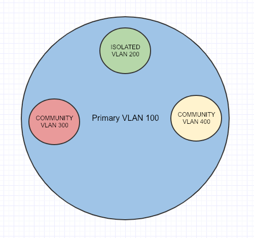
An important port to know about before beginning is called the Promiscuous Port. It acts like a Gateway that routes Primary and Secondary-VLAN traffic, and all Secondary-VLAN traffic must pass through the Promiscuous Port.

Isolated ports can only talk to the Primary VLAN through a Promiscuous Port (Uplink/Gateway Port)

Community ports can talk to each other, if they are in the same Community Secondary-VLAN.

VTP must be set to transparent mode for Private VLAN’s to work.

Here is how to configure Private VLAN’s

First we need to configure the Primary VLAN

TPW-SW1(config)#vlan 100
TPW-SW1(config-vlan)#private-vlan primary 
TPW-SW1(config-vlan)#exit

Configure the Isolated VLAN

TPW-SW1(config)#vlan 200
TPW-SW1(config-vlan)#private-vlan isolated 
TPW-SW1(config-vlan)#exit

Configure the Community VLAN’s

TPW-SW1(config)#vlan 300
TPW-SW1(config-vlan)#private-vlan community 
TPW-SW1(config-vlan)#exit

TPW-SW1(config)#vlan 400
TPW-SW1(config-vlan)#private-vlan community 
TPW-SW1(config-vlan)#exit

Now we have to associate the Primary VLAN to the Isolated and Community VLAN’s

TPW-SW1(config)#vlan 100 
TPW-SW1(config-vlan)#private-vlan association 200 
TPW-SW1(config-vlan)#private-vlan association 300
TPW-SW1(config-vlan)#private-vlan association 400

This is where we configure for fa0/1 as the Promiscuous Port

TPW-SW1(config-if)# int fa0/1 
TPW-SW1(config-if)#switchport mode private-vlan promiscuous

We have to tell the Promiscuous Port that it is associated with the  (Isolated and Community VLAN’s) that it can also see and talk to them appropriately.

TPW-SW1(config-if)#switchport private-vlan host-association 100 200,300,400
TPW-SW1(config-if)#exit

Configure fa0/2 and fa0/7 as the Isolated port, but also about its Primary VLAN 100

TPW-SW1(config-if)# int fa0/2 
TPW-SW1(config-if)#switchport mode private-vlan host
TPW-SW1(config-if)#switchport private-vlan host-association 100 200
TPW-SW1(config-if)#exit

TPW-SW1(config-if)# int fa0/7 
TPW-SW1(config-if)#switchport mode private-vlan host 
TPW-SW1(config-if)#switchport private-vlan host-association 100 200 
TPW-SW1(config-if)#exit

Configure fa0/3 and 4 as community ports, but also about its Primary VLAN 100

TPW-SW1(config)#int range fa0/3 - 4 
TPW-SW1(config-if-range)# 
TPW-SW1(config-if-range)# switchport mode private-vlan host
TPW-SW1(config-if-range)# switchport private-vlan host-association 100 300
TPW-SW1(config-if-range)# exit

Configure fa0/5 and 6 as community ports, but also about its Primary VLAN 100

TPW-SW1(config)#int range fa0/5 - 6 
TPW-SW1(config-if-range)# 
TPW-SW1(config-if-range)# switchport mode private-vlan host
TPW-SW1(config-if-range)# switchport private-vlan host-association 100 400
TPW-SW1(config-if-range)# exit

You can confirm the Private VLAN’s are setup correctly with the following show command

TPW-SW1#show vlan private-vlan

Primary      Secondary    Type                Ports
-------      ---------    -----------------   ----------------------------------
100          200          isolated            fa0/2, fa0/7
100          300          community           fa0/3, fa0/4
100          400          community           fa0/5, fa0/6

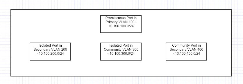
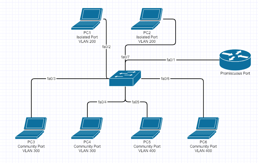
Here is the topology of what was just built.

Here is a table of what can talk to each other

PC

Computer PC1 – Isolated – VLAN 200 PC2 – Isolated – VLAN 200 PC3 – Community VLAN 300 PC4 – Community VLAN 300 PC5 – Community VLAN 400 PC6 – Community VLAN 400
PC1 – Isolated – VLAN 200 YES NO NO NO NO NO
PC2 – Isolated – VLAN 200 NO YES NO NO NO NO
PC3 – Community VLAN 300 NO NO YES YES NO NO
PC4 – Community VLAN 300 NO NO YES YES NO NO
PC5 – Community VLAN 400 NO NO NO NO YES YES
PC6 – Community VLAN 300 NO NO NO NO YES YES


Cisco Switch : VLAN ACL’s (VACL)

This week, I have been studying and configuring VLAN ACL’s. VLAN ACL’s have a use because Regular ACL’s can be used to filter inter-VLAN traffic but not intra-VLAN traffic. Filtering between hosts on the same VLAN require the use of VLAN Access Lists (VACL).

The VACL will do the actual filtering of the traffic, but we still need to write an ACL to identify the traffic. The ACL will be used as a match criteria within the VACL to drop of forward the traffic.

I will show you how to implement a VACL on TPWSW1 that will prevent anyone from telnetting from UserPC1 subnet while allowing all other traffic.

The process  I always follow for doing this is:
1. Build ACL
2. Build VACL
3. Apply VACL to VLAN

Build ACL

I always start a VACL with a regular extended ACL. Try and use descriptive names so when you look at it in 6 month it will mean something.

Create an extended access list named no_telnet_access_list and add an ACL statement that permits Telnet traffic:

TPWSW1(config)#ip access-list extended no_telnet_access_list 
TPWSW1(config-ext-nacl)#permit tcp any any eq telnet

Create an access list named allow_all_traffic and to add an ACL statement that permits all IP traffic:

TPWSW1(config)#ip access-list extended all_traffic
TPWSW1(config-ext-nacl)#permit ip any any

Verify the no_telnet_access_list and the allow_all_traffic access lists you created.

TPWSW1#show access-lists
Extended IP access list allow_all_traffic    
10 permit ip any any
Extended IP access list no_telnet_access_list   
10 permit tcp any any eq telnet

Write the VACL

Create a VLAN access map named vlan_access_map with a sequence number of 10:

TPWSW1(config)#vlan access-map vlan_access_map 10

Configure TPWSW1. Create a match statement that will match an access list named no_telnet_access_list:

TPWSW1(config-access-map)#match ip address no_telnet_access_list

On TPWSW1, Configure an action for the VLAN access map that will drop the packets matched by the no_telnet_access_list access list:

TPWSW1(config-access-map)#action drop

Create a match statement that matches the allow_all_traffic access list and uses sequence number 20:

TPWSW1(config)#vlan access-map vlan_access_map 20
TPWSW1(config-access-map)#match ip address allow_all_traffic

Configure an action for the VLAN access map that will forward the traffic matched by the allow_all_traffic access list:

TPWSW1(config-access-map)#action forward

Verify the access map configuration.

TPWSW1#show vlan access-map
       Vlan access-map “vlan_map”  10  
       Match clauses: IP address: no_telnet_access_list
           Action:
             drop

       Vlan access-map “vlan_map”  20  
       Match clauses:IP address: all_traffic
           Action:
             forward

Apply VACL to VLAN

Apply the vlan_access_map access map to VLAN 5:

TPWSW1(config)#vlan filter vlan_access_map vlan-list 5

Verify the application of the access map to the VLAN.

TPWSW1#show vlan filter
    VLAN Map vlan_map is filtering VLANs:
      5

Verify you cannot access the switch using Telnet. Now obviously you could turn off Telnet other ways, this was purely to demonstrate how powerful these VACL’s can be.

Cisco : SPAN and Remote SPAN

As part of the CCNP Switch you get introduced to a topic called SPAN and Remote SPAN. This feature allows Network Engineers to capture packets flowing to and from a Interface or VLAN and mirror or forward those packets to a Packet Capture Analyzer software such as Wireshark.

Things to be aware of when setting SPAN and RSPAN up:

  • Make sure you destination port is of equivalent speed to the Source port otherwise you could drop packets.
  • A source port cannot be the same as a destination port
  • A destination port can only  be a part of one SPAN session
  • Source ports can be part of a EtherChannel but destinations ports cannot
  • Trunk ports can be setup as source and destination and the default behavior will monitor all active VLAN’s on that port
  • Destination Ports will not participate in STP, CDP, VTP, DTP or LACP
  • The number of SPAN sessions can vary on different switch models

The source can be set to entire VLAN’s (VSPAN) or individual ports. The Source is the port or VLAN you want to monitor.

Here is what the basic SPAN topology would look like:


Here is how to setup the Source SPAN interface.


tpw-sw1(config)#monitor session 1 source interface GigabitEthernet 1/1

The Destination is the port you have the network analyzer connected to.

tpw-sw1(config)#monitor session 1 destination interface GigabitEthernet 1/2

Verify your SPAN port setup.

tpw-sw1#show monitor

Session 1

---------

Type                   : Local Session

Source Ports           :

    Both               : Gi1/1

Destination Ports      : Gi1/2


The behavior is expected on a SPAN port:

tpw-sw1#sh int Gi1/1
FastEthernet1/1 is down, line protocol is down (monitoring)


However SPAN isn’t always going to be local, so luckily for us there is Remote SPAN (RSPAN). This feature allows the mirrored packets to traverse the trunk port to another switch via a separate VLAN. The configuration is fairly straightforward however there are a couple of caveats:

  1. All switches have to be RSPAN capable.
  2. VTP does treat the RSPAN VLAN like a regular VLAN and will propagate that through the VTP domain, but if its not you will have to add them manually to each switch
  3. VTP will prune the VLANS like a regular VLAN
  4. MAC address learning is disabled on the RSPAN VLAN
  5. Source and Destinations will be slightly different on each switch so don’t just copy the commands on each switch.

The topology would look something like this:


Here is the configuration for RSPAN tpw-sw1 – be  aware the destination RSPAN VLAN

tpw-sw1(config)#vlan 4000

tpw-sw1(config-vlan)#remote-span

tpw-sw1(config)#monitor session 1 source interface GigabitEthernet 1/1

tpw-sw1(config)#monitor session 1 destination remote vlan 4000

Verify your work.

tpw-sw1#show monitor

Session 1

---------

Type                   : Local Session

Source Ports           :

    Both               : Gi1/1

Dest RSPAN VLAN     : 4000

Here is the configuration for RSPAN tpw-sw2 – be aware the source is the RSPAN VLAN

tpw-sw2(config)#vlan 4000

tpw-sw2(config-vlan)#remote-span

tpw-sw2(config)#monitor session 1 source remote vlan 4000

tpw-sw2(config)#monitor session 1 destination interface GigabitEthernet 1/2

Verify your work.

tpw-sw2#show monitor

Session 1

---------

Type                   : Local Session

Source RSPAN VLAN        : 4000

Destination Ports     : Gi1/2


If you have a setup similar to below you have to name Remote SPAN VLAN 4000 on all intermediate switches.

Happy SPANNING 🙂


Arista : VARP Configuration

Virtual-ARP or VARP is a routing technique that allows multiple switches or routers to simultaneously route packets from a common Virtual IP (VIP) address in an active/active switch/router configuration. Each switch or router is configured with the same VIP address on the corresponding VLAN interfaces (SVI) and a common virtual MAC address. In MLAG topologies, VARP is preferred over VRRP because VARP does not require traffic to traverse the peer-link to the master router as VRRP would.

A maximum of 500 VIP addresses can be assigned to a single VLAN interface. All virtual addresses on all VLAN interfaces resolve to the same virtual MAC address. However you cannot have a secondary VIP on the same VLAN interface, you can however implement VRRP on the same VLAN interface as VARP.

VARP functions by having each switch respond to ARP and GARP requests for the configured router IP address with the virtual MAC address. The virtual MAC address is only for inbound packets and never used in the source field of outbound packets.

The following commands configures 10.10.10.1 as the virtual IP address for VLAN 10. The Virtual-Router MAC address is entirely invented by you, I had a real issue finding clarification that it was just a made up MAC address, so here is my invented made up Virtual-Router MAC 1010.1010.1010 as the virtual MAC address on both switches. I also ran into an issue where #ip routing had to be enabled.

Here is what the Topology would look like:

Configuration that implements VARP on the first switch

TPW-SW1(config)#ip virtual-router mac-address 1010.1010.1010

TPW-SW1(config)#interface vlan 10

TPW-SW1(config-if-vl10)#ip address 10.10.10.2/24

TPW-SW1(config-if-vl10)#ip virtual-router address 10.10.10.1

Configuration that implements VARP on the second switch

TPW-SW2(config)#ip virtual-router mac-address 1010.1010.1010

TPW-SW2(config)#interface vlan 10

TPW-SW2(config-if-vl10)#ip address 10.10.10.3/24

TPW-SW2(config-if-vl10)#ip virtual-router address 10.10.10.1


The Packet Wizard : Spanning Tree Explained

Spanning Tree Protocol also known as STP

There are many different types of STP but here are a couple of the main ones

STP/802.1D – Original STP
PVST+ – Cisco Improved STP adding per VLAN feature
RSTP/802.1w – Improved STP with a much faster convergence time (Rapid Spanning Tree)
Rapid PVST+ – Cisco improved RSTP adding per VLAN feature

Why Per VLAN STP?
If you have a large network with lots of switches and VLAN’s you can use Per VLAN STP to plan for a more efficient network

Even although there are many versions of STP they all use a very similar set of rules.

What is STP?

STP is a feature used to prevent loops when you are using redundant switches and without STP a loop could form and cause a number of problems on the network.

During a unicast broadcast message (which happen all the time) the switch will forward the frame out of every port except the one it came in on. Therefore if SW1 sends a frame out and SW2 and SW3 receive it then SW2 and SW3 will forward out all ports except the one it came in on.  SW2 sends to SW3 and SW1. SW3 send to SW2 and SW1 and you can see how the loop is now beginning to form. This is known as a broadcast storm, this can kill a switches CPU and Memory usage very quickly.

The second problem is the MAC address being changed all the time as it receives frames. For example SW1 sends a broadcast message, SW2 and SW3 receive it, then forward it out all other ports like in the scenario above. However each switch learns the MAC address of the next switch and assigns that in the MAC address table, but if you consider SW1 sending to SW2 and SW3 and then SW2 and SW3 forwarding those frames and they eventually get back to SW1 but on different ports, then the MAC Address table will change constantly from I know about SW2 on this port,  I now know about SW2 via SW3 on this port, and that can cause unstable MAC address tables.

Another issues is explained below

HOST1  sends data to HOST2, however since SW2 doesn’t know how to get to SW2 it sends frames out all ports, thus sending to SW1 and SW3 so HOST2 receives frames from HOST1 via SW3 and then again via SW1>SW3. This is known as Duplicate Frames.

So how do we fix the issues mentioned above? Thats right Spanning Tree Protocol by blocking one of the redundant paths.

The question now becomes how do the switches decide on that Port to block? STP follow’s strict rules, when deciding what ports to block. 

1) Elect a Root Bridge (ROOT)
2) Place root interfaces into forwarding (FWD)
3) Select Root Port on non-Root Bridge Switches (RP) – this is the best root to the Root Bridge.
4) Non Root Switches decide on a Designated Port (DP)
5) All other ports put into Blocking State (BLK)

On per VLAN STP You could have this on VLAN 10

and this on VLAN 20

I will now cover the port roles and the port states so you know what each is:

ROLES
Root Ports : The best port to get to the Root Bridge

Designated Ports : The Lowest cost alternate best root to the Root Bridge.
Non Designated Ports : All other ports that are in blocking mode.

STATES
Disabled : A Port is shutdown
Blocking : A Port that is blocking traffic
Listening : A Port that is not forwarding and not learning MAC addresses
Learning: A Port that is learning MAC addresses but is not forwarding traffic
Forwarding : A Port that is sending and receiving traffic as normal

When ports change from one Role to another it will go through the Port States. Note also that the Listening and Learning states are transitional and it wont stay on either.

Root Bridge Election

Each switch has and sends messages to each other called Bridge Protocol Data Units (BPDU’s) These BPDU’s contain specific information pertaining to each switch, such as Root Cost, Bridge ID (BID) for Itself and for the Root.  A BID is made up of STP Priority and MAC address, the default value of The BID on SW1 would be 327691111:1111:1111 since 32769 is the default STP priority and the MAC address. The switch with the lowest BID will become the Root Bridge. This is what is looks like before the Root Bridge Election and the exchange of the BPDU’s

This is what it looks like after, when the lowest BID wins.

The ports on each switch now transition into their respective states following the STP Rules as mentioned above.

The ports can change based on the Cost of each link. The port costs are listed below, however in this example we will just be using Gig Ports, but for clarity a FastEthernet Port will be slower than a GigEthernetPort, the faster the port the lower the cost. The Root Port (RP) is the lowest port cost.

Data rate STP cost RSTP cost
(Link Bandwidth) (802.1D-1998) (802.1W-2004, default value)
4 Mbit/s 250 5,000,000
10 Mbit/s 100 2,000,000
16 Mbit/s 62 1,250,000
100 Mbit/s 19 200,000
1 Gbit/s 4 20,000
2 Gbit/s 3 10,000
10 Gbit/s 2 2,000
100 Gbit/s N/A 200
1 Tbit/s N/A 20

This is a quick diagram of how the port costs are worked out to get back to the Root Bridge. SW2 to get to SW1 is 0+4=4 and SW2 via SW3 to SW1 is 4+4=8

Of course there can be ties between multiple connections and STP can be tuned.

Designated Ports are selected by Root Cost the by Lowest BID and then by lowest numbered Interface. Therefor in the diagram above the Designated port would be GigEth1 on SW3 since it is a lower numbered interface than SW2 GigEth2.

All ports that are not Root Ports or Designated Ports are Blocking Ports.

STP Convergence Times

STP:
BPDU/Hello time = 2 secs – Hello messages to each switch to see its still there
Max Age = 20 secs – How long a switch will wait for a response to the Hello message
Listening = 15 secs
Learning = 15 secs

= 52 secs to convergence

From the time a link goes down to convergence it takes a total of 52 Seconds. When STP was designed that was fine but now, this is much too slow which is where Rapid Spanning Tree Comes in.

RSTP:
3 missed BDPU/Hello at 2 sec each = 6 secs
Learning (no listening) = 15 secs

= 21 secs to convergence.

I hope this have given you a good explanation of STP. 


The Packet Wizard : DHCP Troubleshooting

In todays scenario, I am going to walk through some changes I made and troubleshooting steps for when I recently added a moved a old SSID/Subnet off an old legacy wireless network onto a new network same IP space and SSID that requires RADIUS authentication.

These steps can be applied to many different scenarios for troubleshooting DHCP, I just made these ones specific since it was something I recently had to troubleshoot.

Here is a basic diagram of the setup, showing all the moving parts would be overkill for the diagram. The steps on what to do and troubleshooting are below the diagram.

What you will need:

Authentication Server IP

Authentication Secret Key

DHCP Server IP

Subnet and Mask that is being moved

SSID/Subnet being moved

Work and or Troubleshooting that needs to be done:

  1. Add the VLAN to the switches required
  2. Add the virtual interface on the firewall (gateway)
  3. Trunk the new vlan to the switch and configure the ports
  4. Setup DHCP helper to point to the DHCP server
  5. Allow DHCP traffic from the new subnet to the DHCP server
  6. Configure Radius on new Network
  7. Configure new SSID and network settings on Wireless LAN Controller

Cisco/Brocade : Basic Similar Commands

  • Here are some basic switch commands and the Cisco to Brocade differences, even though the OS’s are similar they have some subtle differences.

Task

Cisco

Brocade

Configure a VLAN

Interface vlan 2

Vlan 2

Configure a trunk port

Int fa0/1

Switchport trunk encap dot1q

Switchport mode trunk

Vlan 2

Tagged eth 0/1/1

Vlan 3

Tagged eth 0/1/1

Vlan 4

Tagged eth 0/1/1

Interface ethernet 0/1/1

Dual-mode 1

Configure a access port

Int fa0/1

Switchport access vlan 2

Vlan 2

Untagged eth 0/0/1

Configure an IP address on a VLAN

Int vlan2

Ip address 192.168.1.1 255.255.255.0

Vlan 2

Router interface ve 1

Interface ve1

Ip address 192.168.1.1 255.255.255.0

Configure a range of ports

Int range fa0/1-10

Int eth 0/1/1 to 0/1/5

Configure a port for both voice and data vlans

Int fa0/1

Switchport access vlan2

Switchport voice vlan3

vlan2

Tagged eth 0/1/1

vlan3

Tagged eth 0/1/1

Inter eth 0/1/1

Dual-mode 1

Voice-vlan 3

Inline power

Show the interface status of a port/vlan

Sh int fa0/1

Show int eth 0/1/1

See CDP Neighbors

Show cdp neighbors

Show fdp neighbors

Ruckus/Brocade : Configure Spanning Tree 802.1w/RSTP

I want to point out that Ruckus/Brocade has 2 commands that contradict each other when configuring Spanning Tree:

Brocade(config-vlan-1)#spanning-tree  ?

  802-1w          Enable Rapid Spanning Tree IEEE 802.1w
  rstp                  Enable Rapid Spanning Tree

Since RSTP is the same as 802.1w further clarification is needed.

Brocade(config-vlan-1)#spanning-tree rstp  is a Brocade early implementation of the IEEE 802.1W which provided only a subset of the standard, whereas the

Brocade(config-vlan-1)#spanning-tree  802-1w feature provides the full standard, so basically you should use 802.1w.

How to configure Spanning Tree on Brocade

Ran mainly on a per VLAN basis.

Brocade# conf t
Brocade (config)#vlan 1
Brocade (config-vlan-1)#  spanning-tree 802-1w – enabled spanning tree basic mode
Brocade (config-vlan-1)# show 802-1w – shows spanning tree information
Brocade (config-vlan-1)# spanning-tree 802-1w priority 0 – to designate that switch Root bridge

If you know there is a point to point link between 2 rapid spanning tree devices you have to turn that on at the interface level

Point-to-Point/Uplinks
Brocade (config-vlan-1)#int e 1/1/1
Brocade (config-if-e10000-1/1/1)# spanning-tree 802-1w admin-p2pt-mac – don’t allow for a broadcast domain, assume there is a link between 2 rapid spanning tree root bridges/uplinks ( without this it will fail over in 2 seconds or less, but fail back takes the traditional 30 of listening and learning, but this allows it to fail forward and back in 2 seconds or less

Access/Edge-Ports
Brocade (config-if-e10000-1/1/1)# int e 1/1/3 to 1/1/24

Brocade (config-if-e10000-1/1/3-1/1/24)#  spanning-tree 802-1w admin-edge-port (not really required, just means topology changes on the edge is not going to cause re-convergence on the core links or vice versa

Brocade (config-if-e10000-1/1/3-1/1/24)#  show run – will see spanning tree on the VLAN and the int ports

***DO NOT USE VLAN1 IN PRODUCTION, THIS IS PURELY FOR DEMONSTRATION PURPOSES***

Brocade : Dual Access Ports

Dual Access Ports : Data and Voice

You need to make the port dual-mode port. Configuring a tagged port as dual-mode allows it to accept and transmit both tagged and untagged traffic at the same time. For example, I am going to connect a phone and a laptop to a port 1/1/1. This port is running in dual mode having a tagged membership in VLAN 13 (phone) and untagged membership in VLAN 12 (laptop).

Brocade (config)# vlan 12
Brocade (config-vlan-12)# tagged eth 1/1/1
Brocade (config-vlan-12)# vlan 13
Brocade (config-vlan-13)# tagged eth 1/1/1
Brocade (config-vlan-13)# int eth 1/1/1
Brocade (config-if-e1000-1/1/1)# dual-mode 12 – this command changes from the native vlan to vlan 12 which is for the data port and should be untagged.